

 Ongoing
ATtiny13 / DS18B20 Fan Controller
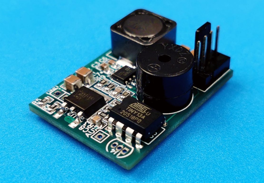
STDATtiny13 / DS18B20 Fan Controller
License
:Public Domain
Description
Features
Intelligent 2- 3- 4-wire Fan Controller based on ATtiny13.
- Up to 8 digital temperature sensors (DS18B20).
- Automatically detects the presence of PWM control (4th fan wire).
- Operates in On/Off or PWM mode.
- 19.5 kHz PWM.
- Rotation control with an attempt to restart in case of a stop.
- Step-down DC-DC converter for fan power supply (up to 38V input, up to 2A output).
- Linear voltage regulator for MCU power supply.
- Audio alerts.
The controller regulates the fan speed using PWM, and the full PWM range (0 - 100%) fits into the temperature range of 25°C - 40°C. Unlike the ATtiny10-based project, this device can poll up to 8 sensors and uses a single 12-38 volt power supply. ATtiny13 has 64 bytes of EEPROM on board, which we can use to store the serial numbers of the connected sensors. In the case of connecting a fan without PWM control or without a speed sensor (2- 3-wire fans), the control is carried out for a temperature threshold of 30°C: if the hottest sensor's temperature below this limit, then a logical 0 is set at the 2nd pin of the chip, and if higher, then 1. This pin is used to control the EN pin of the DC-DC converter.
The controller also issues an audible alarm when the temperature of the hottest sensor exceeds the threshold of 50°C.
The module is designed for use in cooling systems of various household and professional equipment.
See the detailed review of the project on my YT-channel (English subtitles): https://youtu.be/DCnN7JbptWM
Details
For MCU Flash ROM programming you will need a USBasp programmer (or any other that supports the TPI - Tiny Programming Interface), which is connected according to this schematic:

The programming itself is performed from the Arduino IDE, with the ATtiny13 core installed in it (see the links below).
Please note that by default, the 1st pin of the microcontroller is used for the RESET signal (active level is low). To use this pin as a GPIO pin, you must rewrite the microcontroller's fuses (see the command below). After you do this, you will no longer be able to flash the chip with a regular programmer. To program such a chip, you'll need 12V to be applied to the RESET pin.
Also note that the code is written for the MCU clock frequency of 5 MHz. This means that in the Arduino IDE, in the Tools->Clock menu, you should set the value to "4.8 MHz internal osc.", and then preferably calibrate the value of the OSCCAL register in the code for your specific exemplar of the chip. This can be done, for example, by uncommenting "Pulse generation" section of the code and measuring the duration of the pulses using an oscilloscope.
Links
Code - https://github.com/DmitryMuravyev/ATtiny13-DS18B20-Fan-Controller
Datasheet ATtiny13 - https://ww1.microchip.com/downloads/en/DeviceDoc/ATtiny13A-Data-Sheet-DS40002307A.pdf
Datasheet DS18B20 - https://datasheets.maximintegrated.com/en/ds/DS18B20.pdf
Tips and Tricks to Optimize Code for 8-bit AVR - https://ww1.microchip.com/downloads/en/AppNotes/doc8453.pdf
1-Wire protocol (Book of iButton standards) - https://pdfserv.maximintegrated.com/en/an/AN937.pdf
USBasp firmware - https://www.fischl.de/usbasp/
USBasp firmware update guide - https://www.electronics-lab.com/project/usbasp-firmware-update-guide/
MicroCore (ATtiny13) for Arduino IDE - https://github.com/MCUdude/MicroCore
AVR high-voltage serial programming for ATtiny - https://github.com/tsaarni/avr-high-voltage-serial-programming
Commands
Fuse programming (0xFE - set RSTDISBL bit): avrdude -C ..\etc\avrdude.conf -c usbasp -P usb -B 32 -p attiny13 -v -U lock:w:0xFF:m -U hfuse:w:0xFE:m
Components
DS18B20 Temperature Sensor - https://ali.ski/Alu_j-
SMD Capacitor Sample Book - https://ali.ski/l-lE9
SMD Resistor Sample Book - https://ali.ski/6YxlCV
SOT-23 SMD Transistor Sample Book - https://ali.ski/qAAOV
Active Buzzer 5V - https://ali.ski/oXOilQ
KF2510 3+1P Fan connector - https://ali.ski/kyrey
Design Drawing
BOM
 Clone
CloneProject Members
 Empty
Empty
Comment