Editor Version ×
Standard

1.Easy to use and quick to get started

2.The process supports design scales of 300 devices or 1000 pads

3.Supports simple circuit simulation

4.For students, teachers, creators

Profession

1.Brand new interactions and interfaces

2.Smooth support for design sizes of over 5,000 devices or 10,000 pads

3.More rigorous design constraints, more standardized processes

4.For enterprises, more professional users

Ongoing

STD XMoto STM32

License: CC-BY-NC 3.0

Mode: Editors' pick

Cloned from XMoto STM32 (stacked)

  • 1.6k
  • 0
  • 2
Update time: 2022-01-22 14:13:07
Creation time: 2020-12-04 16:50:29
Description
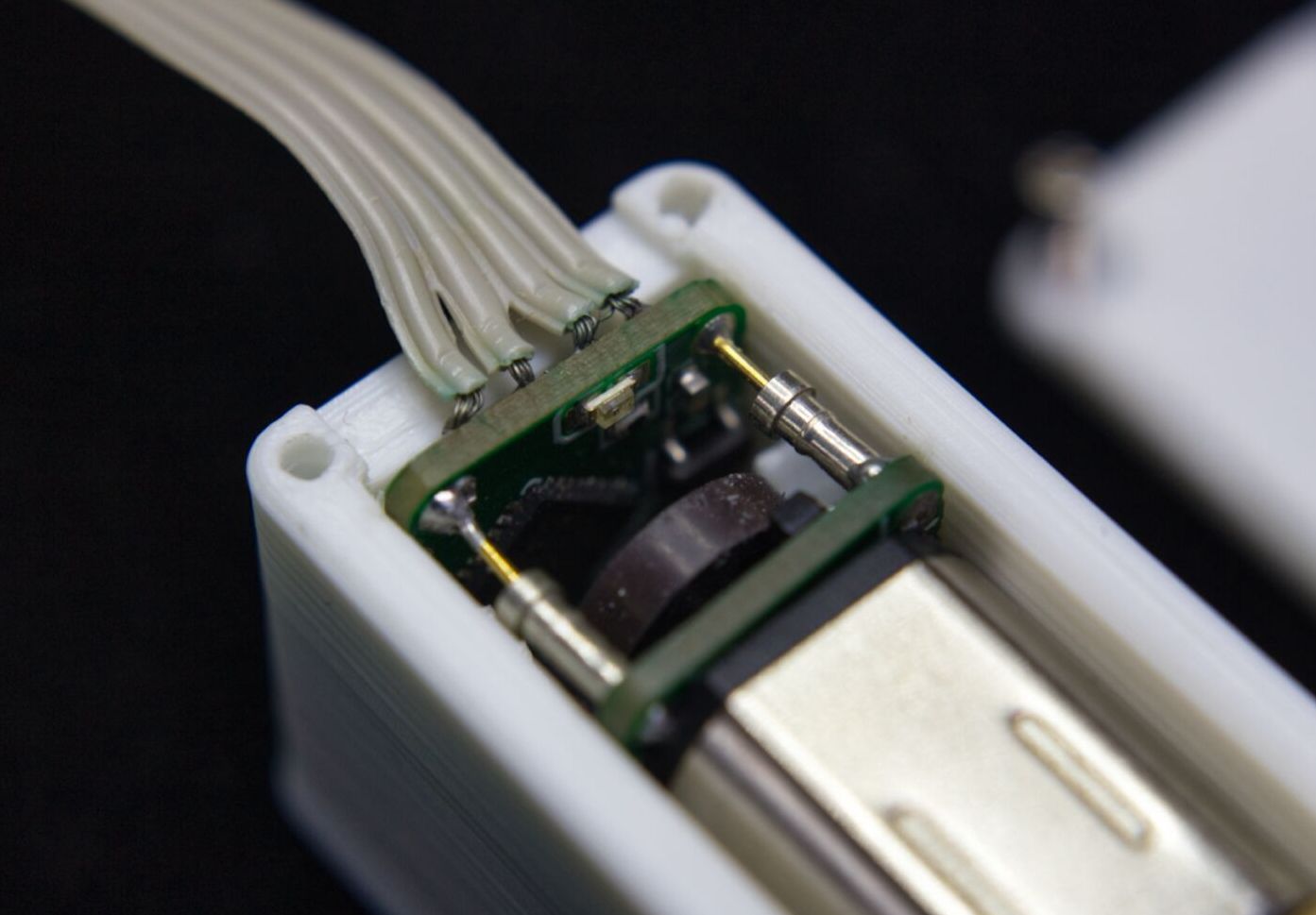
But let's compare a stepper motor with my solution. This is a normal stepper motor, which is used in many projects like 3D printers and the like. We have a step angle of 1.8 degrees, a holding force of about 3.7 kg on one centimeter. That basically means the stepper motor can hold 3.7 kg, with a one centimeter lever. At this maximum load, the motor needs 1.5Amps on each phase. The motor weighs 255 grams. \-\-\-\-\- Now the second motor comes into the round ... a gear motor with extended shaft from Pololu. We have here the "HighPower" version with 1.6A maximum current and a gear ratio of 380 to 1. This one manages an impressive 5kg holding power on the centimeter and weighs just 10 grams. Well, with the additional technology and housing, we might get to 20 grams. You can see what I'm getting at, this much smaller motor creates more holding power and uses less power. But that's not all, it also controls the position of the motor and has a servo function that constantly corrects the position of the motor automatically. Of course, we still have to make a few changes to the technology before this motor understands step as well as direction signals ... so let's unscrew the little guy and take a closer look at the technology behind it. First we take off the cover, as you can see, I soldered 2 small PCBs in a stacking process to the contacts of the motor. Now I want to introduce them to you. For this I have not yet soldered PCB's here on the table. \-\-\-\-\- The first PCB is soldered directly to the motor and is called "XMoto Driver". In the middle there is a hole for the through shaft, on this shaft there is a magnetic disk with 3 embedded magnets each ... this generate 12 steps per revolution with 2 hall sensors. The Hall sensors are mounted in a 90 degree angle on the driver and send their signals to the second PCB, which I will introduce in a moment. Of course we still need a DC motor driver, I chose the DRV8837 for this. This one comes in a tiny 2mm package and is able to control the motor's direction and speed via PWM signals. It is also capable of stopping the motor and holding the load. \-\-\-\-\- All well and good, but now how do we turn a DC motor into a stepper motor? This is done by the second board, which is connected to the driver via the large contacts with plus and minus as well as a plug-in socket strip and is called XMOTO STM. As the name already suggests, a microcontroller is installed here, which takes over the task of a stepper motor driver. At one input it listens to the step impulses, at the other one to the direction signals (STEP and DIR) and moves the motor via the motor driver accordingly. It constantly compares whether the motor is in the correct position, if not, the position is actively controlled. So it is a servo function that always corrects the position of the motor. The signals between the boards are transmitted via a 1mm pin header, this includes the signals of the sensors and the PWM signals, with which the motor is controlled. Since the motor needs 6V, but our microprocessor needs 3.3V, I added a very efficient stepdown converter. Additionally a LED to see if the motor is under power and for diagnostic messages. \-\-\-\-\-\- The whole thing in a housing and ready is our DC stepper motor. So let's test if this really works. As a simple example I installed the mother of all MotionControl software called "GRBL" on an "Arduino Nano" as delivered. If you look at the pinout of the software, you can tap the step signals for the X-axis at PIN D2 and direction signals at pin D5. Then connect 5V to plus and ground to minus and control the motor via serial console. \-\-\-\-\- So, that should be it for now. In my next video I will talk about programming, configuration and other things. If you are interested in this topic, please subscribe or give me a thumbs up. To not miss anything, just activate the bell below this video. I wish you a Merry Christmas and a Happy New Year Your Frank
Design Drawing
schematic diagram
1 /
PCB
1 /
The preview image was not generated, please save it again in the editor.
Project Attachments
Empty
Project Members
Target complaint
Related Projects
Change a batch
Loading...
Add to album ×

Loading...

reminder ×

Do you need to add this project to the album?

服务时间

周一至周五 9:00~18:00
  • 0755 - 2382 4495
  • 153 6159 2675

服务时间

周一至周五 9:00~18:00
  • 立创EDA微信号

    easyeda

  • QQ交流群

    664186054

  • 立创EDA公众号

    lceda-cn