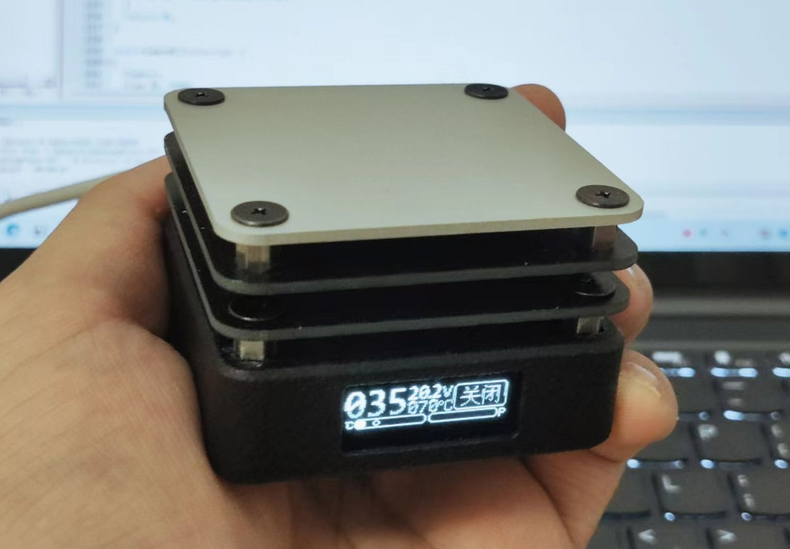
 Completed
[PD Protocol | Good appearance.]mini Heating Station
PRO [PD Protocol | Good appearance.]mini Heating Station
License
:GPL 3.0
Description


Protocol chip using IP2721, quick charging voltage 20V.
The display uses a 0.91’ OLED module.
The main controller chip is STC8H3K32S.
Due to the small size of the heating table, the screen takes up almost all of the front of the body, Therefore, the keys can only be set on the back of the body.
1.Software
1.On the default page, the real-time temperature is displayed in the upper left corner. In the middle, the voltage and set temperature are displayed. In the upper right corner, the heating status (constant temperature, heating, off) is shown.
2.In the lower left corner, the actual temperature and set temperature are displayed. In the lower right corner, the PWM duty cycle (real-time power) is shown.
5.On the setting page, pressing the left and right keys for a short time can adjust the options.

PID parameter setting interface↑
The configurable options include the three parameters of PID.

Temperature setting interface↑
Maximum and minimum temperature limits.

At the same time, the display mode can be changed. The display modes include detailed information display mode and temperature curve mode. The detailed information interface will display information such as temperature, power supply voltage, heating status, power, etc. (The picture at the beginning of the article is the detailed information display mode).

Real-time temperature curve display interface
When changed to the real-time temperature curve mode, most of the information on the main page is omitted. Only the actual temperature, set temperature, and heating switch are retained. However, the real-time temperature curve will be displayed. It is updated once every second and can record temperature information for about 100 seconds. The dotted line is the set temperature.
Settings are recorded in the eeprom and will not be lost in a power failure.

Before programming the program, change the IRC frequency to 35MHz. Then click "Download/Program" to proceed.
二、Hardware
- M3*12mm double-pass studs * 4; // Neither too long nor too short.
- M3*5+6mm single-pass studs * 4; // It is not recommended to be too short or too long. It can be a little longer appropriately.
- M3*5 double-pass studs * 8; // It is not recommended to be too short or too long. It can be a little longer appropriately.
- M3*3 flat head screws*28; // screw length <= (short double pass stud length + 2*1.6).
- M3*8 flat head screws*4;//can't be any shorter, can be slightly longer, 8<=length<=10.
- M3*3 Copper Nut/Inlaid Nut*12.
- P100 test pins * 2; // Use test pins to connect the main board and the heating plate. It is recommended to use round heads with a length of about 33mm.
- PT1000 platinum resistance; // Used for temperature measurement.


Motherboard

Close-up of the relative position of the test pin hole and the screen.

Close-up of the test pin after installing the aluminum substrate.
Use thermal conductive adhesive to stick the thermistor under the aluminum substrate (with the aluminum surface facing up). The resistance of the aluminum substrate is about 6 ohms. When powered by 20V, the power is about 65W. If you want to increase the power, please increase the width of the aluminum substrate traces by yourself.
The screen connector and thermistor connector on the main control board can choose to weld sockets or directly solder wires. Pay attention to the wire sequence of the screen interface. The thermistor is non-polar.
Install the key into the housing.
Screw the long screws and copper nuts onto the bottom plate and place it at the bottom of the housing (pay attention to the direction). Then install the main board into the housing from the side of the button and fix it on the bottom plate with copper nuts.
Install the 12mm stud into the housing, tighten the bottom plate screws, and connect the screen and thermistor to the main board.
Install the top plate. Use 5+6 single-pass studs to fix the top plate on the housing. Then install the heat insulation plate in turn. (Pay attention to the direction of the reserved test pin hole).
Put in the test pin (the test pin does not need to be soldered). Solder the thermistor connecting wire and tighten the screws to fix the aluminum substrate.
Completed!
The open-source design drawing has a screen panel. Use JLCPCB panel printing, which can be used as a protective panel for the screen.

BOM is subject to the PCB. The automatically generated BOM may be incorrect.
9.26: Fixed the display bug of the progress bar and the key bug.
Designed by 小O和小Q (from OSHWHub)
Link:https://oshwhub.com/littleoandlittleq/bian-xie-jia-re-tai
Design Drawing
 The preview image was not generated, please save it again in the editor.
 Empty
Empty


Comment