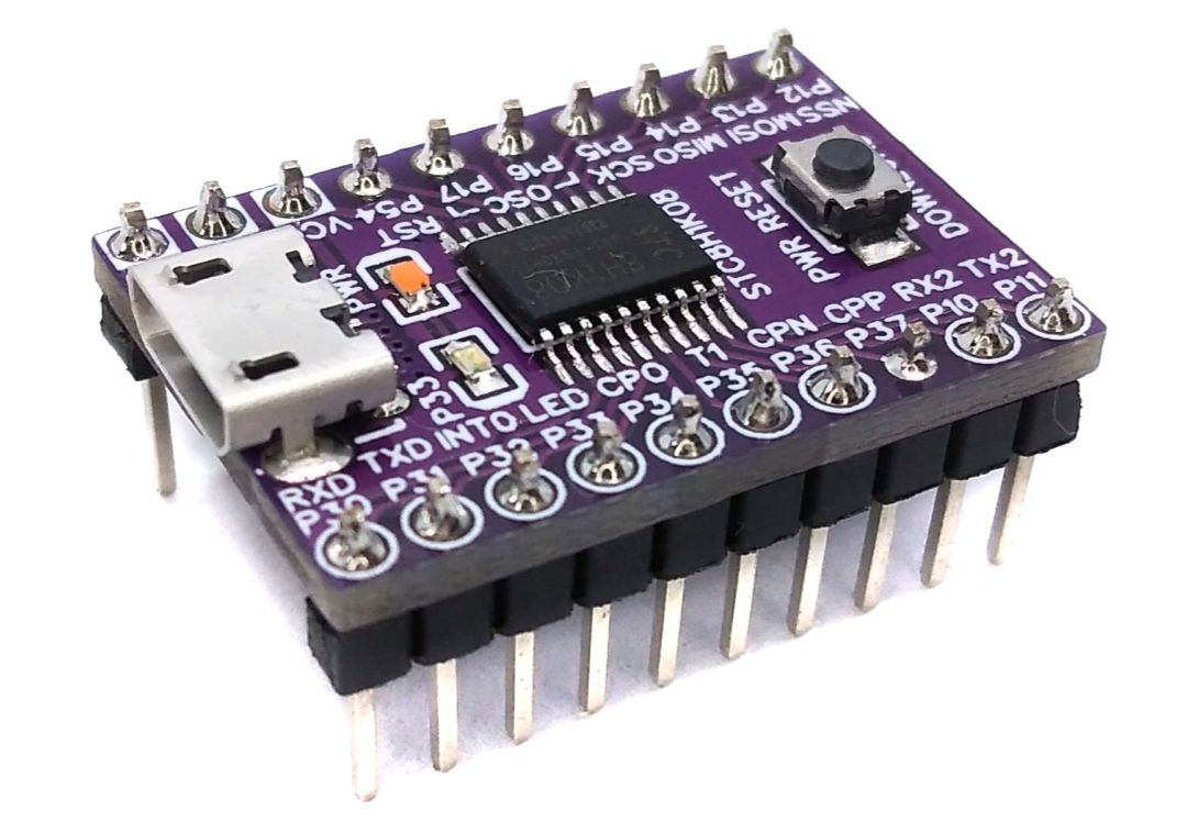
# STC8H1K08-36I-TSSOP20 Development Board
Development board for the STC8H1K08 ultra-cheap 8-bit 8051 core microcontroller with integrated USB-to-serial adapter which can also be used to upload firmware utilizing the factory built-in serial bootloader.
- Project Files (Github): https://github.com/wagiminator/Development-Boards/tree/main/STC8H1K08_DevBoard
![STC8H1K08_DevBoard_pic1.jpg](https://raw.githubusercontent.com/wagiminator/Development-Boards/main/STC8H1K08_DevBoard/documentation/STC8H1K08_DevBoard_pic1.jpg)
# Pinout
![STC8H1K08_DevBoard_pinout.png](https://raw.githubusercontent.com/wagiminator/Development-Boards/main/STC8H1K08_DevBoard/documentation/STC8H1K08_DevBoard_pinout.png)
# The STC8H1K08 Family of 8-bit 8051 Microcontrollers
## Overview
The STC8H1K08 series is a cost-effective family of 8-bit microcontrollers with an ultra-high speed 8051 core that is compatible with the MCS51 instruction set. These microcontrollers offer an average instruction speed that is approximately 12 times faster than the traditional 8051, with most instructions requiring only one clock cycle for execution. They support clock frequencies of up to 36MHz, operate within a voltage range of 1.9V to 5.5V, and come equipped with standard peripherals such as a 10-bit ADC, analog comparator, multiple timers, PWM, UART, SPI, and I2C. Additionally, these microcontrollers feature a built-in bootloader, allowing firmware to be uploaded directly via UART without the need for an extra programming device.
## Features
- Ultra-high-speed 8051 core with single clock per machine cycle (1T)
- Fully compatible instruction set with the traditional 8051
- Maximum 36MHz system main frequency
- Up to 17KB of Flash for user code (CODE)
- 128 bytes internal direct access SRAM (DATA)
- 128 bytes internal indirect access SRAM (IDATA)
- 1024 bytes internal extended SRAM (XDATA)
- 4KB EEPROM, can be erased more than 100,000 times
- Operating voltage: 1.9V - 5.5V
- Internal high-precision RC clock (IRC), adjustable to a max of 36MHz, error ±0.3%
- Internal 32KHz low-speed oscillator (LSI) with a large error
- External 4MHz - 33MHz oscillator or external clock (HSE)
- Power-on reset, programmable low-voltage detector
- 17 interrupt sources and 4 interrupt priority levels
- Multiple low-power modes: Idle, Stop
- Up to 17 GPIOs (P1.0 - P1.7, P3.0 - P3.7, P5.4)
- 4 modes for all GPIOs: quasi-bidirectional, push-pull output, open-drain, high-impedance input
- 8 channels enhanced 16-bit PWM, complementary output with dead time, external pulse width measurement
- 3x 16-bit timers with multiple operating modes
- 1x watchdog timer
- 2x UART interface, max baud rate F_CPU/4
- 1x SPI interface, master and slave mode
- 1x I2C interface, master and slave mode
- 1x 10-bit ADC, 9 channels + internal 1.19V reference voltage, 500ksps
- 1x set of comparators
- Factory-built-in UART bootloader
# Compiling, Programming and Debugging
## SDCC Toolchain
For compiling install the SDCC compiler. On Linux (Debian-based), this can be done with the following command:
```
sudo apt install build-essential sdcc
```
## Factory built-in UART Bootlader
The MCU has an embedded bootloader with UART interface, which can be used to upload firmware using the CH340E USB-to-serial adapter integrated into the board.
The Python tool [stc8isp.py](https://github.com/wagiminator/MCU-Flash-Tools) included with the example software can be used for this purpose. In order for this ISP tool to work, Python3 must be installed on your system. To do this, follow these [instructions](https://www.pythontutorial.net/getting-started/install-python/). In addition [PySerial](https://github.com/pyserial/pyserial) must be installed. On Linux (Debian-based), all of this can be done with the following commands:
```
sudo apt install python3 python3-pip
python3 -m pip install pyserial
```
You can also utilize the manufacturer's proprietary programming tool, [STC ISP](https://www.stcmicro.com/rjxz.html), for programming the MCU.
To upload firmware through the USB port, press and release the DOWNLOAD button when prompted by the ISP software to perform a power cycle. This button interrupts the power supply to the MCU, forcing it to enter bootloader mode.
## Arduino IDE Support
An Arduino core for the STC8H series can be found [here](https://github.com/ma6254/Arduino_Core_STC).
# References, Links and Notes
- [EasyEDA Design Files](https://oshwlab.com/wagiminator)
- [STC Product Page](https://stcmicro.com/stc/stc8h1k08.html)
- [STC ISP Software](https://www.stcmicro.com/rjxz.html)
- [MCU Templates](https://github.com/wagiminator/MCU-Templates)
- [MCU Flash Tools](https://github.com/wagiminator/MCU-Flash-Tools)
- [Arduino Support](https://github.com/ma6254/Arduino_Core_STC)
![STC8H1K08_DevBoard_pic2.jpg](https://raw.githubusercontent.com/wagiminator/Development-Boards/main/STC8H1K08_DevBoard/documentation/STC8H1K08_DevBoard_pic2.jpg)
![STC8H1K08_DevBoard_pic3.jpg](https://raw.githubusercontent.com/wagiminator/Development-Boards/main/STC8H1K08_DevBoard/documentation/STC8H1K08_DevBoard_pic3.jpg)
# License
![license.png](https://i.creativecommons.org/l/by-sa/3.0/88x31.png)
This work is licensed under Creative Commons Attribution-ShareAlike 3.0 Unported License.
(http://creativecommons.org/licenses/by-sa/3.0/)