Editor Version ×
Standard

1.Easy to use and quick to get started

2.The process supports design scales of 300 devices or 1000 pads

3.Supports simple circuit simulation

4.For students, teachers, creators

Profession

1.Brand new interactions and interfaces

2.Smooth support for design sizes of over 5,000 devices or 10,000 pads

3.More rigorous design constraints, more standardized processes

4.For enterprises, more professional users

Ongoing

STD ATtiny85 USB-C Tester
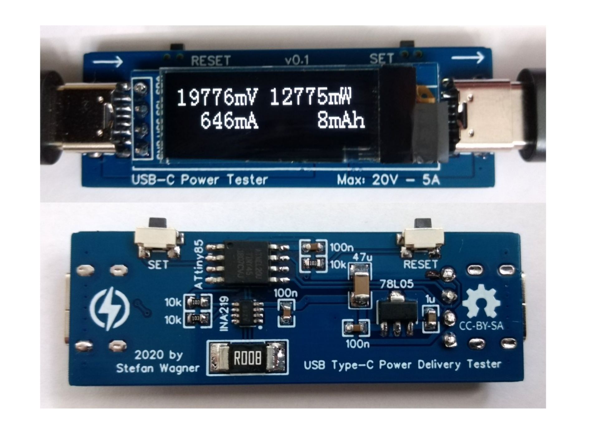
License: CC-BY-SA 3.0

Mode: Editors' pick

  • 5.9k
  • 0
  • 26
Update time: 2022-01-15 12:20:16
Creation time: 2020-06-20 11:31:31
Description
# Overview Simple USB-C Power Delivery Tester based on ATtiny25/45/85 and INA219. The device measures voltage, current, power, energy, capacity and displays the values on an OLED screen. You can switch between different screens by pressing the SET button. - Project Video (YouTube): https://youtu.be/QKx8Vn_IfjU - Firmware (Github): https://github.com/wagiminator/ATtiny85-USB-C-Tester ![pic1.jpg](https://raw.githubusercontent.com/wagiminator/ATtiny85-USB-C-Tester/master/documentation/USB_C_Tester_pic1.jpg) # Hardware ## USB Connectors The device is equipped with a USB-C receptacle (PCB version a) or plug (PCB version b) for the input and a USB-C receptacle for the output, so that it can be plugged between the power supply and the consumer. CC1 and CC2 communication channels are passed through so that supply and consumer can negotiate the bus power. ![pic2.jpg](https://raw.githubusercontent.com/wagiminator/ATtiny85-USB-C-Tester/master/documentation/USB_C_Tester_pic2.jpg) ![pic4.jpg](https://raw.githubusercontent.com/wagiminator/ATtiny85-USB-C-Tester/master/documentation/USB_C_Tester_pic4.jpg) ## Voltage and Current Measurement An [INA219](https://www.ti.com/lit/ds/symlink/ina219.pdf) is used to measure voltage and current. The INA219 is a current shunt and power monitor with an I²C-compatible interface. The device monitors both shunt voltage drop and bus supply voltage, with programmable conversion times and filtering. A programmable calibration value, combined with an internal multiplier, enables direct readouts of current in amperes. The selected shunt resistance of 8mΩ enables both a very small influence on the circuit and a measurement with a resolution of 1mA. For an accurate measurement, a shunt resistor with a low tolerance (1% or better) should be selected. ## User Interface The user interface utilizes two buttons and a [128x64 pixels OLED display](http://aliexpress.com/wholesale?SearchText=128+64+0.96+oled+new+4pin). An [ATtiny24/45/85](https://ww1.microchip.com/downloads/en/DeviceDoc/Atmel-2586-AVR-8-bit-Microcontroller-ATtiny25-ATtiny45-ATtiny85_Datasheet.pdf) microcontroller handles the user interface as well as the calculation and display of the values. ![pic3.jpg](https://raw.githubusercontent.com/wagiminator/ATtiny85-USB-C-Tester/master/documentation/USB_C_Tester_pic3.jpg) # Software ## Basic Principle The INA219 continuously measures current and voltage and transmits the values to the ATtiny via I²C. From this, the ATtiny calculates the other values and displays them on the OLED screen. ## I²C OLED Implementation The I²C protocol implementation is based on a crude bitbanging method. It was specifically designed for the limited resources of ATtiny10 and ATtiny13, but it works with some other AVRs (including the ATtiny25/45/85) as well. The functions for the OLED are adapted to the SSD1306 OLED module, but they can easily be modified to be used for other modules. In order to save resources, only the basic functionalities which are needed for this application are implemented. For a detailed information on the working principle of the I²C OLED implementation visit [TinyOLEDdemo](https://github.com/wagiminator/attiny13-tinyoleddemo). ## Accuracy of Time and Capacity Determination The internal oscillator of the ATtiny is used to determine energy and capacity. The accuracy of the internal oscillator is +/-10% with the factory calibration. This can be improved to +/-2% or better by [manual calibration](https://github.com/wagiminator/ATtiny84-TinyCalibrator). The calibration value determined in this way can be set in the source code. ## Compiling and Uploading Since there is no ICSP header on the board, you have to program the ATtiny either before soldering using an [SOP adapter](https://aliexpress.com/wholesale?SearchText=sop-8+150mil+adapter), or after soldering using an [EEPROM clip](https://aliexpress.com/wholesale?SearchText=sop8+eeprom+programming+clip). The [AVR Programmer Adapter](https://github.com/wagiminator/AVR-Programmer/tree/master/AVR_Programmer_Adapter) can help with this. ### If using the Arduino IDE - Make sure you have installed [ATtinyCore](https://github.com/SpenceKonde/ATTinyCore). - Go to **Tools -> Board -> ATtinyCore** and select **ATtiny25/45/85 (No bootloader)**. - Go to **Tools** and choose the following board options: - **Chip:** ATtiny25 or 45 or 85 (depending on your chip) - **Clock:** 1 MHz (internal) - **B.O.D.Level:** B.O.D. enabled (2.7V) - Leave the rest at the default settings - Connect your programmer to your PC and to the ATtiny. - Go to **Tools -> Programmer** and select your ISP programmer (e.g. [USBasp](https://aliexpress.com/wholesale?SearchText=usbasp)). - Go to **Tools -> Burn Bootloader** to burn the fuses. - Open USB_C_Tester sketch and click **Upload**. ### If using the precompiled hex-file - Make sure you have installed [avrdude](https://learn.adafruit.com/usbtinyisp/avrdude). - Connect your programmer to your PC and to the ATtiny. - Open a terminal. - Navigate to the folder with the hex-file. - Execute the following command (if necessary replace "usbasp" with the programmer you use): ``` avrdude -c usbasp -p t85 -U lfuse:w:0x62:m -U hfuse:w:0xd5:m -U efuse:w:0xff:m -U flash:w:usb_c_tester.hex ``` ### If using the makefile (Linux/Mac) - Make sure you have installed [avr-gcc toolchain and avrdude](http://maxembedded.com/2015/06/setting-up-avr-gcc-toolchain-on-linux-and-mac-os-x/). - Connect your programmer to your PC and to the ATtiny. - Open the makefile and change the chip if you are not using ATtiny85 and the programmer if you are not using usbasp. - Open a terminal. - Navigate to the folder with the makefile and the Arduino sketch. - Run "make install" to compile, burn the fuses and upload the firmware. # Operating Instructions 1. Connect the device between a power supply and a consumer. Due to the internal structure of the USB-C cables, it may be necessary to change the orientation of one of the cable plugs if you are using the 2-receptacle version of the device. 2. Use the SET button to switch between the different screens. 3. Use the RESET button to reset all values. ![pic7.jpg](https://raw.githubusercontent.com/wagiminator/ATtiny85-USB-C-Tester/master/documentation/USB_C_Tester_pic7.jpg) ![pic8.jpg](https://raw.githubusercontent.com/wagiminator/ATtiny85-USB-C-Tester/master/documentation/USB_C_Tester_pic8.jpg) # Characteristics |Parameter|Value| |-|-| |Voltage|5V - 20V| |Current|max 5A| |Voltage Measurement Resolution|4mV| |Current Measurement Resolution|1mA| # References, Links and Notes 1. [UBS-A Version](https://github.com/wagiminator/ATtiny85-USB-Tester) 2. [ATtiny25/45/85 Datasheet](https://ww1.microchip.com/downloads/en/DeviceDoc/Atmel-2586-AVR-8-bit-Microcontroller-ATtiny25-ATtiny45-ATtiny85_Datasheet.pdf) 3. [INA219 Datasheet](https://www.ti.com/lit/ds/symlink/ina219.pdf) 4. [SSD1306 Datasheet](https://cdn-shop.adafruit.com/datasheets/SSD1306.pdf) ![pic5.jpg](https://raw.githubusercontent.com/wagiminator/ATtiny85-USB-C-Tester/master/documentation/USB_C_Tester_pic5.jpg) ![pic6.jpg](https://raw.githubusercontent.com/wagiminator/ATtiny85-USB-C-Tester/master/documentation/USB_C_Tester_pic6.jpg) # License ![license.png](https://i.creativecommons.org/l/by-sa/3.0/88x31.png) This work is licensed under Creative Commons Attribution-ShareAlike 3.0 Unported License. (http://creativecommons.org/licenses/by-sa/3.0/)
Design Drawing
schematic diagram
1 /
PCB
1 /
The preview image was not generated, please save it again in the editor.
ID Name Designator Footprint Quantity
1 OLED 0.91 OLED I2C OLED 0.91 1
2 TS24CA RESET,SET SW-SMD_TS24CA 2
3 10k R4,R1,R3 0603 3
4 78L05 U3 SOT-89-3_L4.5-W2.5-P1.50-LS4.2-BR 1
5 ATtiny85 U1 SOIC-8_208MIL 1
6 USB-C Plug USB1 USB-C-SMD_PLUG 1
7 USB-TYPE-C-6PIN USB3,USB2 USB-C-SMD-6P 2
8 INA219 U2 SOT-23-8 1
9 100n C3,C1,C5 0603 3
10 47u C2 1206 1
11 1u C4 0603 1
12 R008 R2 2512 1

Unfold

Project Attachments
Order File name Download times
1

USB-C_Tester_case_3dprint.zip

12
Project Members
Target complaint
Related Projects
Change a batch
Loading...
Add to album ×

Loading...

reminder ×

Do you need to add this project to the album?

服务时间

周一至周五 9:00~18:00
  • 0755 - 2382 4495
  • 153 6159 2675

服务时间

周一至周五 9:00~18:00
  • 立创EDA微信号

    easyeda

  • QQ交流群

    664186054

  • 立创EDA公众号

    lceda-cn