Editor Version ×
Standard

1.Easy to use and quick to get started

2.The process supports design scales of 300 devices or 1000 pads

3.Supports simple circuit simulation

4.For students, teachers, creators

Profession

1.Brand new interactions and interfaces

2.Smooth support for design sizes of over 5,000 devices or 10,000 pads

3.More rigorous design constraints, more standardized processes

4.For enterprises, more professional users

Ongoing

STD ATtiny814 USB PD Adapter
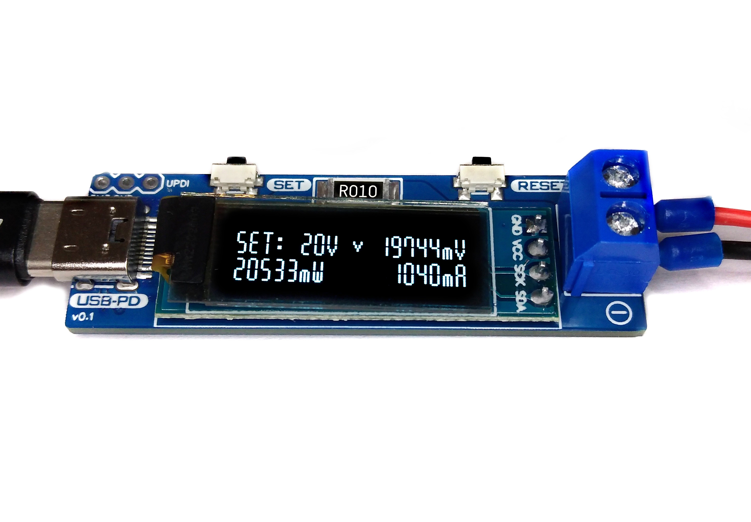
License: CC-BY-SA 3.0

Mode: Editors' pick

  • 2.4k
  • 7
  • 7
Update time: 2022-11-24 18:49:49
Creation time: 2022-08-02 07:53:49
Description
# Overview The USB PD Adapter is a USB Power Delivery trigger and monitoring board that enables you to use almost any USB Type-C PD power supply to run your projects with different selectable voltages and high currents. Important values such as voltage, current, power and energy are displayed on the OLED. The USB PD Adapter is based on the cheap and easy-to-use CH224K multi fast charging protocol power receiving chip, the INA219 voltage and current sensor IC, and an ATtiny204, 214, 404, 414, 804, 814, 1604 or 1614 microcontroller. * Firmware (Github): https://github.com/wagiminator/ATtiny814-USB-PD-Adapter ![pic1.jpg](https://raw.githubusercontent.com/wagiminator/ATtiny814-USB-PD-Adapter/master/documentation/USB_PD_Adapter_pic1.jpg) # Hardware ## Schematic ![wiring.png](https://raw.githubusercontent.com/wagiminator/ATtiny814-USB-PD-Adapter/master/documentation/USB_PD_Adapter_wiring.png) ## 78L33 Voltage Regulator The 78L33 is a simple and inexpensive voltage regulator that can convert input voltages up to 30V to an output voltage of 3.3V with an output current of up to 200mA and a dropout voltage of 1.7V. The 78L33 supplies all elements of the circuit with 3.3V. ## CH224K USB PD Power Receiving Chip The CH224K is a USB PD power receiving protocol chip, which integrates PD3.0/2.0, BC1.2 and other fast charging protocols, automatically detects VCONN and analog E-Mark chips, supports up to 100W power, and has built-in PD communication module. It also integrates output voltage detection internally to support overheating and overvoltage protection. It features: * 4V to 22V input voltage * PD3.0/2.0, BC1.2 and other fast charging protocols * USB Type-C PD, positive and negative insertion detection and automatic switching * E-Mark simulation, automatically detects VCONN, supports 100W power PD request * requested voltage can be dynamically adjusted through a variety of methods * high integration of single chip, simplified peripheral and low cost * built-in over-voltage and over-temperature protection module The output voltage is selected via three configuration pins of the CH224K, which are connected directly to the ATtiny and is set according to the following table: | Output Voltage | CFG1 | CFG2 | CFG3 | | -------------- | ---- | ---- | ---- | | 5V | 1 | - | - | | 9V | 0 | 0 | 0 | | 12V | 0 | 0 | 1 | | 15V | 0 | 1 | 1 | | 20V | 0 | 1 | 0 | The CH224K's PG pin is open-drain, pulling the input to ground when the requested voltage has been successfully negotiated with the USB PD power supply. It can be used to drive an indicator LED or a high-side P-channel MOSFET for power path control. Here this pin is connected directly to the ATtiny, which can query the status with the help of an internal pull-up resistor. ## INA219 Current/Power Monitor The INA219 is a current shunt and power monitor with an I²C-compatible interface. The device monitors both shunt voltage drop and bus supply voltage, with programmable conversion times and filtering. A programmable calibration value, combined with an internal multiplier, enables direct readouts of current in amperes. The selected shunt resistance of 10mΩ enables both a very small influence on the circuit and a measurement with a resolution of 1mA. For an accurate measurement, a shunt resistor with a low tolerance (1% or better) should be selected. The INA219 is used here to measure the output voltage and output current. It communicates with the ATtiny via I²C. ## ATtiny Microcontroller The ATtiny microcontroller handles the user interface, the control of the CH224K and INA219, and the calculation and display of the measured values. The user interface utilizes two buttons and an SSD1306 128x32 pixels OLED display. In this application, the ATtiny runs at only 1MHz to keep power consumption low and thus avoid overheating of the 78L33 voltage regulator, especially at 20V output voltage. The following microcontrollers can be used: ATtiny204, 214, 404, 414, 804, 814, 1604 or 1614. However, since the firmware in the current version already requires almost 2KB of flash (depending on the compiler settings), the use of an ATtiny202 or ATtiny212 is not recommended, since there are hardly any reserves left for future upgrades. ![hardware.png](https://raw.githubusercontent.com/wagiminator/ATtiny814-USB-PD-Adapter/master/documentation/USB_PD_Adapter_hardware.png) # Compiling and Uploading the Firmware ## If using the Arduino IDE * Open your Arduino IDE. * Make sure you have installed [megaTinyCore](https://github.com/SpenceKonde/megaTinyCore). * Go to **Tools -> Board -> megaTinyCore** and select **ATtiny1614/1604/814/804/414/404/214/204**. * Go to **Tools** and choose the following board options: * **Chip:** choose the chip you have installed * **Clock:** 1 MHz internal * Leave the rest at the default settings. * Connect your [programmer](https://github.com/wagiminator/AVR-Programmer) to your PC and to the UPDI header on the board. Make sure the programmer works with 3.3V. * Go to **Tools -> Programmer** and select your UPDI programmer. * Go to **Tools -> Burn Bootloader** to burn the fuses. * Open the sketch and click **Upload**. ## If using the makefile (Linux/Mac) * Connect your [programmer](https://github.com/wagiminator/AVR-Programmer) to your PC and to the UPDI header on the board. Make sure the programmer works with 3.3V. * Download [AVR 8-bit Toolchain](https://www.microchip.com/mplab/avr-support/avr-and-arm-toolchains-c-compilers) and extract the sub-folders (avr, bin, include, ...) to /software/tools/avr-gcc. To do this, you have to register for free with Microchip on the download site. * Open a terminal. * Navigate to the folder with the makefile and the sketch. * Run `DEVICE=attiny814 PROGRMR=serialupdi PORT=/dev/ttyUSB0 make install` to compile, burn the fuses and upload the firmware (change DEVICE, PROGRMR and PORT accordingly). # Operating Instructions 1. Connect the USB PD Adapter to a USB Type-C PD power supply using a USB-C cable. 2. Use the SET button to select the desired output voltage. An hourglass appears on the display while the device is communicating with the power supply. If the negotiation was successful, a tick is displayed and the desired voltage is present at the output. 3. Connect the device to the power consumer via the output screw terminal. 4. Use the RESET button to clear the energy counter. ![operation.png](https://raw.githubusercontent.com/wagiminator/ATtiny814-USB-PD-Adapter/master/documentation/USB_PD_Adapter_operation.png) # References, Links and Notes 1. [78L33 Datasheet](https://datasheet.lcsc.com/lcsc/2204181745_Shikues-78L33_C2999140.pdf) 2. [CH224K Datasheet](https://datasheet.lcsc.com/lcsc/2204251615_WCH-Jiangsu-Qin-Heng-CH224K_C970725.pdf) 3. [INA219 Datasheet](https://www.ti.com/lit/ds/symlink/ina219.pdf?ts=1662832146107) 4. [ATtiny814 Datasheet](https://ww1.microchip.com/downloads/aemDocuments/documents/MCU08/ProductDocuments/DataSheets/ATtiny417-814-816-817-DataSheet-DS40002288A.pdf) 5. [SSD1306 Datasheet](https://cdn-shop.adafruit.com/datasheets/SSD1306.pdf) 6. [CH224K USB PD Decoy](https://github.com/wagiminator/Power-Boards/tree/master/USB-PD_Decoy_CH224K) 7. [TI Primer on USB PD](https://www.ti.com/lit/wp/slyy109b/slyy109b.pdf) 8. [128x32 OLED on Aliexpress](http://aliexpress.com/wholesale?SearchText=128+32+0.91+oled) ![pic2.jpg](https://raw.githubusercontent.com/wagiminator/ATtiny814-USB-PD-Adapter/master/documentation/USB_PD_Adapter_pic2.jpg) ![pic3.jpg](https://raw.githubusercontent.com/wagiminator/ATtiny814-USB-PD-Adapter/master/documentation/USB_PD_Adapter_pic3.jpg) # License ![license.png](https://i.creativecommons.org/l/by-sa/3.0/88x31.png) This work is licensed under Creative Commons Attribution-ShareAlike 3.0 Unported License. (http://creativecommons.org/licenses/by-sa/3.0/)
Design Drawing
schematic diagram
1 /
PCB
1 /
The preview image was not generated, please save it again in the editor.
Project Attachments
Empty
Project Members
Target complaint
Related Projects
Change a batch
Loading...
Add to album ×

Loading...

reminder ×

Do you need to add this project to the album?

服务时间

周一至周五 9:00~18:00
  • 0755 - 2382 4495
  • 153 6159 2675

服务时间

周一至周五 9:00~18:00
  • 立创EDA微信号

    easyeda

  • QQ交流群

    664186054

  • 立创EDA公众号

    lceda-cn