Editor Version ×
Standard

1.Easy to use and quick to get started

2.The process supports design scales of 300 devices or 1000 pads

3.Supports simple circuit simulation

4.For students, teachers, creators

Profession

1.Brand new interactions and interfaces

2.Smooth support for design sizes of over 5,000 devices or 10,000 pads

3.More rigorous design constraints, more standardized processes

4.For enterprises, more professional users

Ongoing

STD ATtiny13 TinyProbe

License: CC-BY-SA 3.0

Mode: Editors' pick

  • 26.8k
  • 3
  • 59
Update time: 2023-07-24 07:06:38
Creation time: 2020-08-22 10:02:46
Description
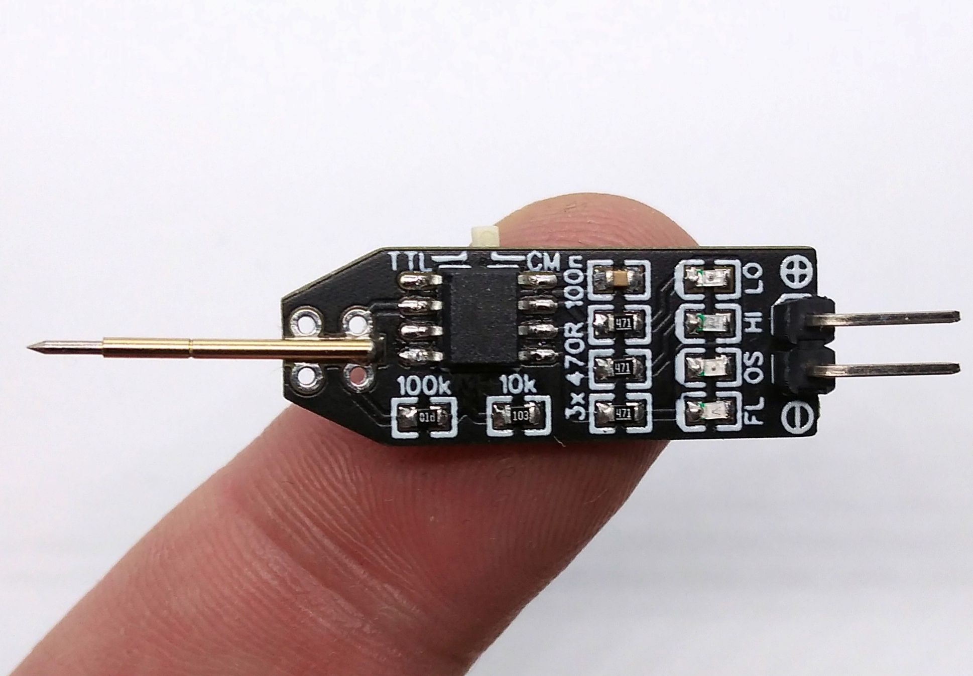
# Overview TinyProbe is a very simple 5V logic probe for TTL and CMOS logic based on ATtiny13a. The probe can detect high (HI), low (LO), floating (FL) and oscillating (OS) signals and displays them via four LEDs. - Project Video (YouTube): https://youtu.be/mwY1OOxqLTI - Firmware (Github): https://github.com/wagiminator/ATtiny13-TinyProbe ![pic1.jpg](https://raw.githubusercontent.com/wagiminator/ATtiny13-TinyProbe/master/documentation/TinyProbe_pic1.jpg) # Hardware The basic wiring is shown below: ![wiring.png](https://raw.githubusercontent.com/wagiminator/ATtiny13-TinyProbe/master/documentation/TinyProbe_wiring.png) GND must be connected to ground of the test board, VCC to 5 Volts. In order to keep the device as simple as possible, input protection has been dispensed with. # Software After setting up the GPIO pins, the ADC and the pin change interrupt, the tests are carried out in the main loop. ## Checking the TTL / CMOS Selection Switch First the position of the TTL / CMOS switch is queried. Although this switch is connected to the RESET pin of the ATtiny, it does not trigger a RESET, as the voltage on the pin never drops below 40% VCC due to the voltage divider. Depending on the switch position, the voltage is VCC or VCC / 2. The threshold values for the detection of a HIGH or LOW signal are set accordingly. ![levels.png](https://raw.githubusercontent.com/wagiminator/ATtiny13-TinyProbe/master/documentation/TinyProbe_levels.png) ```c // define logic levels for TTL and CMOS at 5V #define TTL_LOW 164 // ADC value for 0.8V #define TTL_HIGH 409 // ADC value for 2.0V #define CMOS_LOW 307 // ADC value for 1.5V #define CMOS_HIGH 716 // ADC value for 3.5V // check logic level selection switch and set high/low thresholds accordingly valLow = TTL_LOW; // set low value for TTL valHigh = TTL_HIGH; // set high value for TTL ADMUX = 0b00000000; // set ADC0 against VCC ADCSRA |= 0b01000000; // start ADC conversion while(ADCSRA & 0b01000000); // wait for ADC conversion complete valSwitch = ADC; // get ADC value if (valSwitch 500Hz oscillation) PCMSK = 0b00000000; // turn off interrupt on probe pin ``` ```c // pin change interrupt service routine ISR(PCINT0_vect) { isOscillating = OSC_DUR; // oscillating signal on pin change } ``` In order to detect low-frequency oscillation, the isHigh / isLow flags are compared with the previous measurement. A change is evaluated as an oscillation, unless there is floating at the same time. ```c // check low frequency oscillation if (!isFloating && ((isHigh && lastLow) || (isLow && lastHigh))) isOscillating = OSC_DUR; lastHigh = isHigh; lastLow = isLow; ``` ## Checking for Floating In order to recognize whether a FLOATING signal is present, the input is measured once with an activated 100k pullup (PB4 HIGH) and once with an activated 100k pulldown resistor (PB4 LOW). If the two measurements differ, the isFLOATING flag is set. For the subsequent measurement with the ADC, the 100k is deactivated by setting PB4 to INPUT. ```c // check if probe is floating by testing the behavior when pulling up/down isFloating = PINB; // get input values (line is already pulled up) PORTB &= 0b11101111; // pull down probe line _delay_us(10); // wait a bit isFloating &= (~PINB); // get inverse of input values isFloating &= 0b00001000; // mask the probe line (PB3) DDRB &= 0b11101111; // set pull pin to input (disable pull) _delay_us(10); // wait a bit ``` ## Checking the Logic State In order to recognize whether there is a HIGH or LOW signal at the PROBE, the applied voltage is measured with the analog to digital converter (ADC) and compared with the threshold values selected based on the switch position. The isLow and isHigh flags are set accordingly. ```c // read voltage on probe line and check if it's logic high or low ADMUX = 0b00000011; // set ADC3 against VCC ADCSRA |= 0b01000000; // start ADC conversion while(ADCSRA & 0b01000000); // wait for ADC conversion complete valProbe = ADC; // get ADC value isHigh = (valProbe > valHigh); // check if probe is logic high isLow = (valProbe Board -> MicroCore** and select **ATtiny13**. - Go to **Tools** and choose the following board options: - **Clock:** 1.2 MHz internal osc. - **BOD:** BOD 2.7V - **Timing:** Micros disabled - Connect your programmer to your PC and to the ATtiny. - Go to **Tools -> Programmer** and select your ISP programmer (e.g. [USBasp](https://aliexpress.com/wholesale?SearchText=usbasp)). - Go to **Tools -> Burn Bootloader** to burn the fuses. - Open TinyProbe.ino and click **Upload**. ### If using the precompiled hex-file - Make sure you have installed [avrdude](https://learn.adafruit.com/usbtinyisp/avrdude). - Connect your programmer to your PC and to the ATtiny. - Open a terminal. - Navigate to the folder with the hex-file. - Execute the following command (if necessary replace "usbasp" with the programmer you use): ``` avrdude -c usbasp -p t13 -U lfuse:w:0x2a:m -U hfuse:w:0xfb:m -U flash:w:tinyprobe.hex ``` ### If using the makefile (Linux/Mac) - Make sure you have installed [avr-gcc toolchain and avrdude](http://maxembedded.com/2015/06/setting-up-avr-gcc-toolchain-on-linux-and-mac-os-x/). - Connect your programmer to your PC and to the ATtiny. - Open the makefile and change the programmer if you are not using usbasp. - Open a terminal. - Navigate to the folder with the makefile and sketch. - Run "make install" to compile, burn the fuses and upload the firmware. # References, Links and Notes 1. [ATtiny13A Datasheet](http://ww1.microchip.com/downloads/en/DeviceDoc/doc8126.pdf) 2. [Logic Guide by TI](https://www.ti.com/lit/sg/sdyu001ab/sdyu001ab.pdf) ![pic2.jpg](https://raw.githubusercontent.com/wagiminator/ATtiny13-TinyProbe/master/documentation/TinyProbe_pic2.jpg) ![pic3.jpg](https://raw.githubusercontent.com/wagiminator/ATtiny13-TinyProbe/master/documentation/TinyProbe_pic3.jpg) # License ![license.png](https://i.creativecommons.org/l/by-sa/3.0/88x31.png) This work is licensed under Creative Commons Attribution-ShareAlike 3.0 Unported License. (http://creativecommons.org/licenses/by-sa/3.0/)
Design Drawing
schematic diagram
1 /
PCB
1 /
The preview image was not generated, please save it again in the editor.
Project Attachments
Empty
Project Members
Target complaint
Related Projects
Change a batch
Loading...
Add to album ×

Loading...

reminder ×

Do you need to add this project to the album?

服务时间

周一至周五 9:00~18:00
  • 0755 - 2382 4495
  • 153 6159 2675

服务时间

周一至周五 9:00~18:00
  • 立创EDA微信号

    easyeda

  • QQ交流群

    664186054

  • 立创EDA公众号

    lceda-cn