

 Completed
Mesure courant AC v2.1.1
License
:CERN Open Hardware License
Description
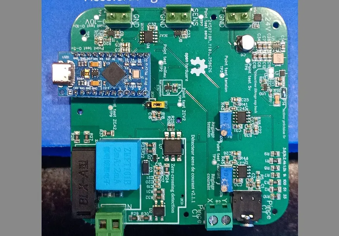
Detection of the Direction and Value of an Alternating Current with an Arduino Pro Micro
This project aims to design a simple, reliable, and cost-effective system to measure both the RMS (Root Mean Square) value and the direction of an alternating current (AC), using an Arduino Pro Micro, an SCT-013-000 current clamp, and an AC voltage transformer.
The SCT-013-000 clamp measures current without direct contact by clamping around a conductor. It generates an analog signal proportional to the current flowing through the cable. This signal is then conditioned (attenuated and centered at 2.5 V) to be read by the Arduino’s analog input A2. At the same time, a step-down voltage transformer (ZMP01B 1000:1000 AC) powers a second circuit that generates a sinusoidal image of the mains voltage, also centered at 2.5 V and connected to input A1.
The core processing is handled by the Arduino Pro Micro, which samples both analog signals and calculates their RMS values, while also analyzing their phase shift to determine the direction of the current (incoming or outgoing). A common 2.5 V reference point is applied to input A0.
A zero-crossing detection system based on the Robodyn system (ZCV1) can be used on Arduino pin D7, or alternatively, a system based on comparing the mid-point and the voltage image (ZCV2).
Zero-crossing detection of the current is also available on pin D3 (ZCA2), using a comparison between the midpoint and the current signal image.
A hardware-based current direction detection is available on pin D2 and through an external terminal block, by comparing the opposition between the ZCV2 and ZCA2 signals. When injecting energy, the output is mostly high (approximately 5 V RMS), and when consuming energy, the output is a 50 Hz square wave (approximately 2.5 V RMS).
Thanks to this approach, the system can detect whether energy is flowing towards a load or being fed back into the grid, making it particularly suitable for photovoltaic installations or advanced home automation applications. The setup is non-intrusive, inexpensive, and easily adaptable to various environments.
The project also includes a filtered PWM output to generate an analog voltage proportional to the measured current, as well as a non-blocking serial display based on millis() for real-time monitoring without disrupting the sampling cycle.
Design Drawing
BOM
 Clone
CloneProject Members
 Empty
Empty
Comment