

 Ongoing
PD Puck - 0.6V~48V Variable PSU (240W max)
STDPD Puck - 0.6V~48V Variable PSU (240W max)
License
:CERN Open Hardware License
Description
Specifications
Power
Input: 3.5V ~ 48V (Terminal Block/USB-C)
Switching Frequency: 153.85kHz
Buck Converter IC: LM5143
Channel 1
Vout1: 3.3V
Vout1 p-p: 9.23mV
Iout1: 2A
Channel 2
Vout2: 0.6V ~ Vin-0.8V (Terminal Block)
Vout2 Setpoint Resolution: 10mV
Vout2 p-p: 25.39mV
Iout2: 5A
USB
Protocol: USB-C PD3.1
Controller IC: HUSB238A (placeholder IC since it's not commonly available)
Power Range: SPR, PPS, EPR, AVS
Microcontroller
Module: ESP32-C3-MINI-1U-H4
LEDs
Vin
3.3V
Vout
Custom LED - MCU
What is the PD Puck?
Many of us are carrying usb-c chargers and power banks around with us everywhere, so why can't we use them to power our electronics projects. The aim of this project was to create a compact and portable variable powersupply which can provide up to 240W by using standard usb-c chargers. This should allow for more flexibilty when prototyping/troubleshooting needs to leave the cozy confines of the lab bench by allowing us to use a power bank. It also reduces the amount of space your benchtop variable powersupply takes up on your already cluttered workbench. No matter where you work (client site, home, field testing, classroom, makerspace) the PD Puck is always with you, just like your phone charger.
Why not use a standard usb-c trigger?
Two reasons:
1. Compatibility: USB-C chargers come in many shapes, sizes and specs. Some of them offer PPS (negotiation of a variable Voltage) but many don't. This is why I chose not to rely on PPS for a variable power output and instead maintain compatibility across all usb-c pd chargers.
2. Power rating: The PD3.1 specification allows for up to 240W (48V@5A) to be negotiated but even though the announcement was made in 2021 we have still not seen any off-the-shelf ICs being rated for the full 240W PD. That being said, while this tool will likely be mostly used for lower power applications I am designing it with the eventual arrival of 240W systems in mind to avoid a redesign down the road.
Improvements
- Add exposed grounding strip on bottom side for EMI Shielding
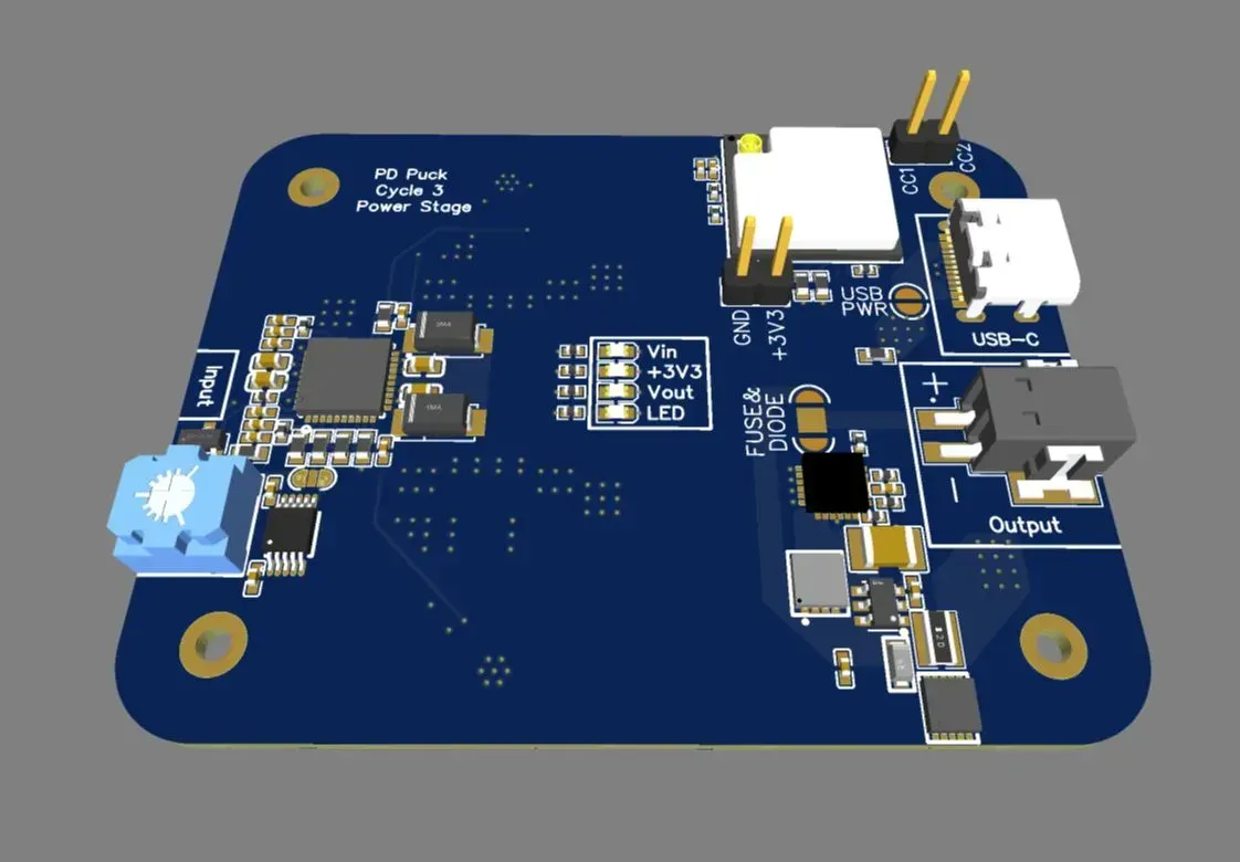
3D Model
Top View

Bottom View

Design Drawing
BOM
 Clone
CloneProject Members
 Empty
Empty
Comment