

 Ongoing
iSpindel Falcon Tube
STDiSpindel Falcon Tube
License
:Public Domain
Description

Overview
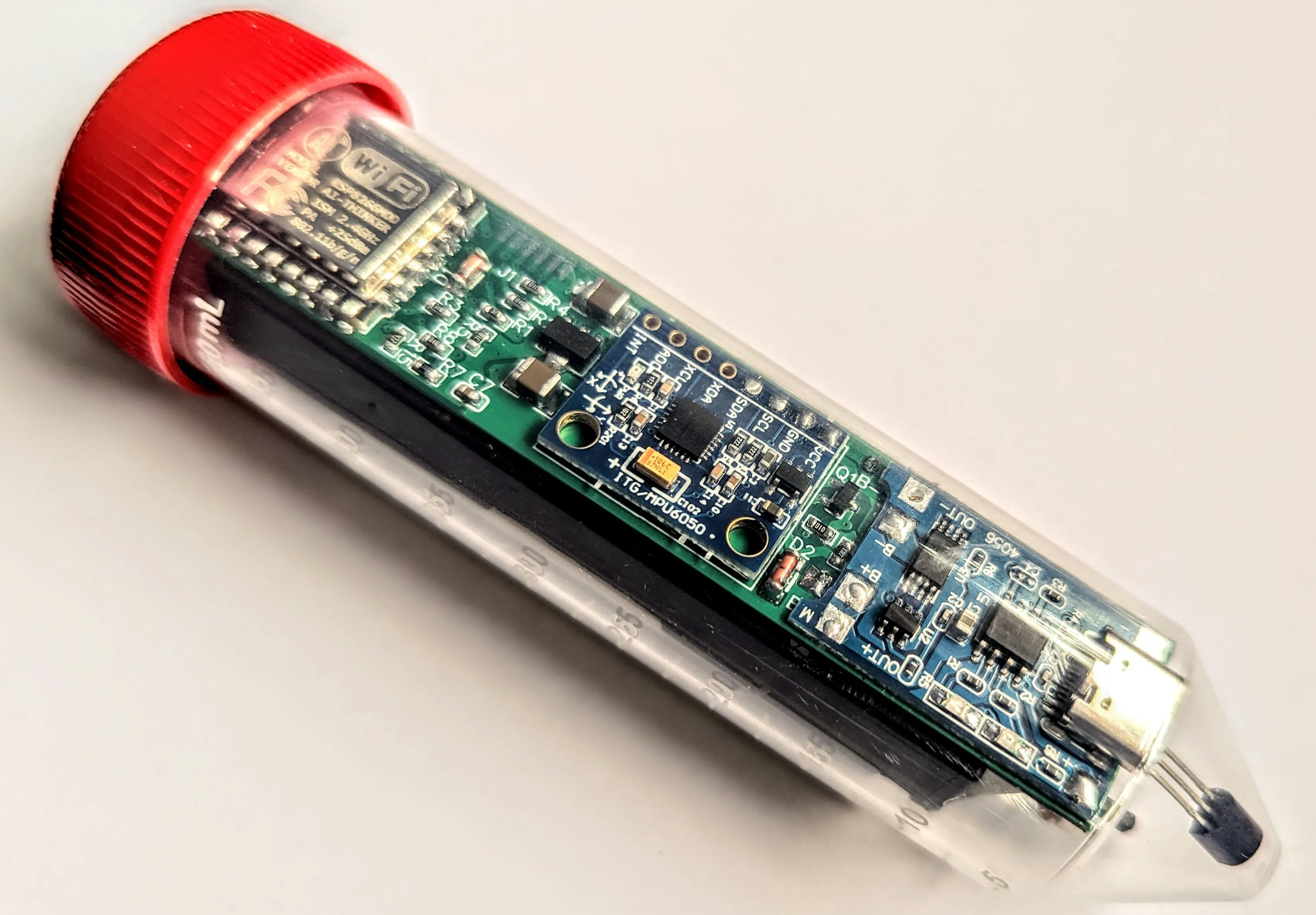
This is a modified iSpindel:
- Uses ESP-12F (ESP8266MOD) instead of WeMos D1 Mini
- Charges correctly from USB while ESP is on (decoupled by a MOSFET)
- Fits into a 50ml Falcon tube
How to build
The build is straight forward, but dues to size constaints I had to make some unorthodox layout choices :)
All the parts, and especially the prebuilt modules (ESP, accelerometer, charger) must be soldered directly to the PCB, without using through pins, because the height of the board must be kept to a minimum.
The battery holder is a single 18650 battery case, with wires, like this one. It is attached to the PCB using double-sided tape:

The battery holder wires must be soldered to the B+ and B- pads. Again, because of size constraints, the wires must be routed through the inside of the case, and the case must be drilled in a few places to expose the pads underneath:

The DS18B20 temperature sensor must be soldered to the SMD pads on the bottom layer, not through-hole. After soldering, its pins must be bent slightly so that the part fits into the Falcon tube, while also touching its wall. This will ensure a faster heat transfer from the wort to the sensor, improving the response time (and maybe accuracy):

The power switch can be of any type, as long as it fits into the enclosure. It must be soldered to the ONOFF pads on the bottom layer.
I actually soldered it to a pair of insulated wires, and the wires to the pads, to allow me to move it around. After soldering, I used a glue gun and a lot of glue to mount it to the battery holder and the board, to make sure it stays in place when operated:

After building the circuit and fitting it into the Falcon tube, it was time for a test - and I found out something that should have been obvious: it wouldn't float! The Falcon tube is too tight and there's not enough room for air around the circuit to keep it buoyant.
The solution was to glue a bottle cap to the cap of the Falcon tube. I again used a liberal amount of hot glue to make sure the assembly was water-tight. Hot glue is non-toxic, so it should be safe to use in wort.

It now floats! Time to flash and calibrate it.

Software
The circuit uses a differnt set of pins than the original iSpindel to connect to the accelerometer module. For this reason, you will need to use a forked version of the project. Everything else (including instructions) is the same as the original.
Happy brewing!
Design Drawing
BOM
 Clone
CloneProject Members
 Empty
Empty
Comment