

 Completed
Jelly Fish Light - PCB Structure
PROJelly Fish Light - PCB Structure
License
:Public Domain
Description
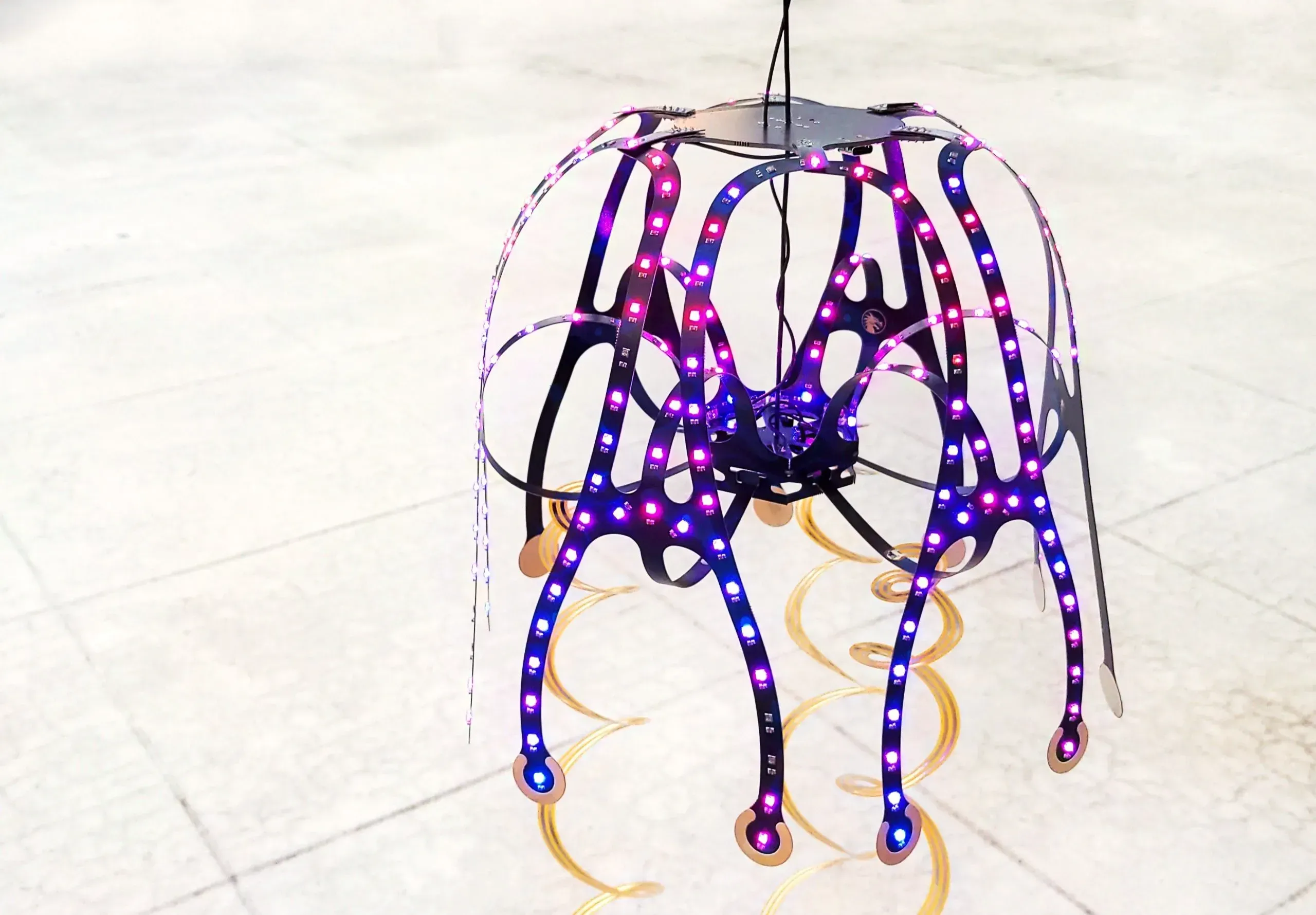
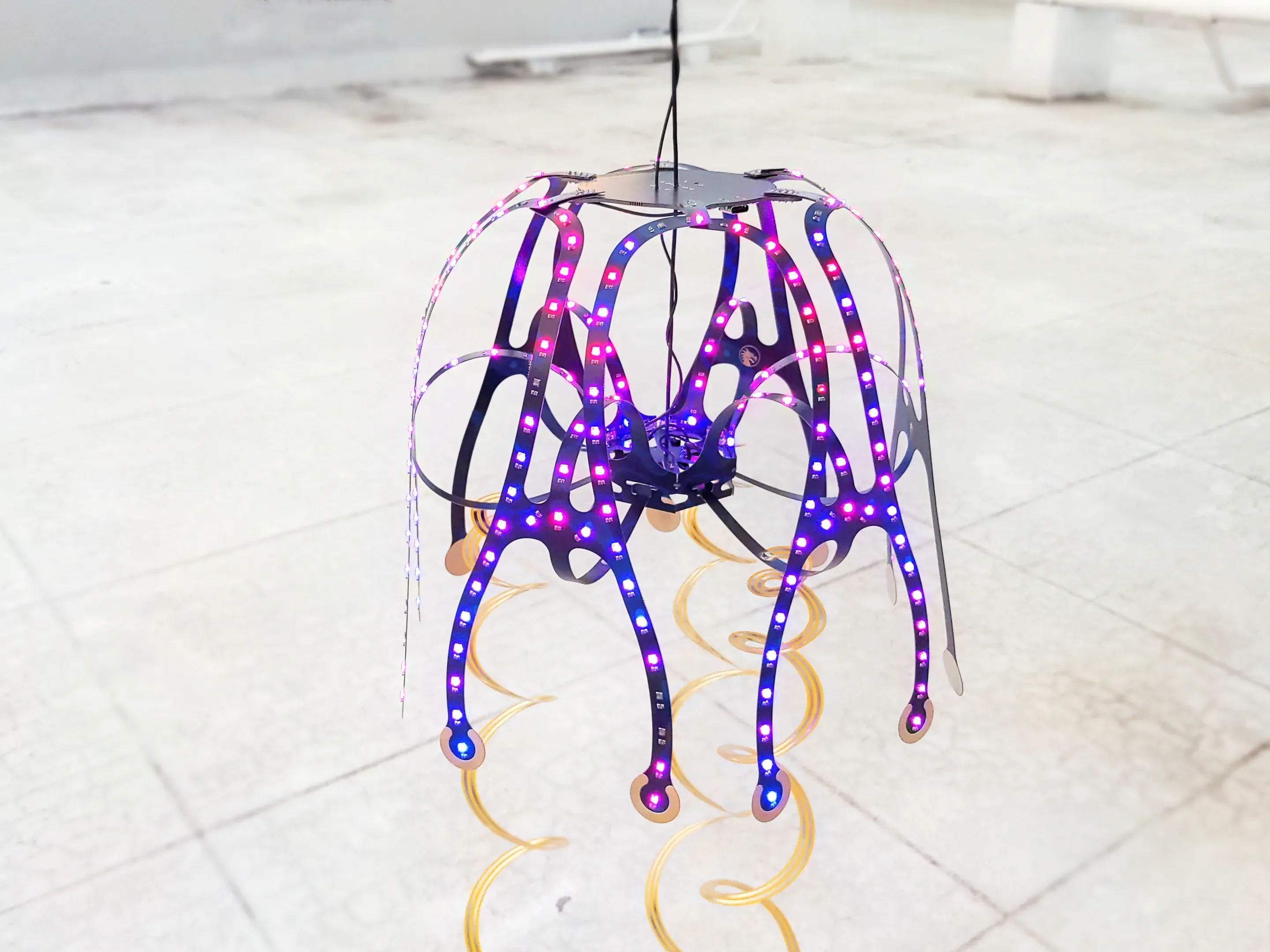
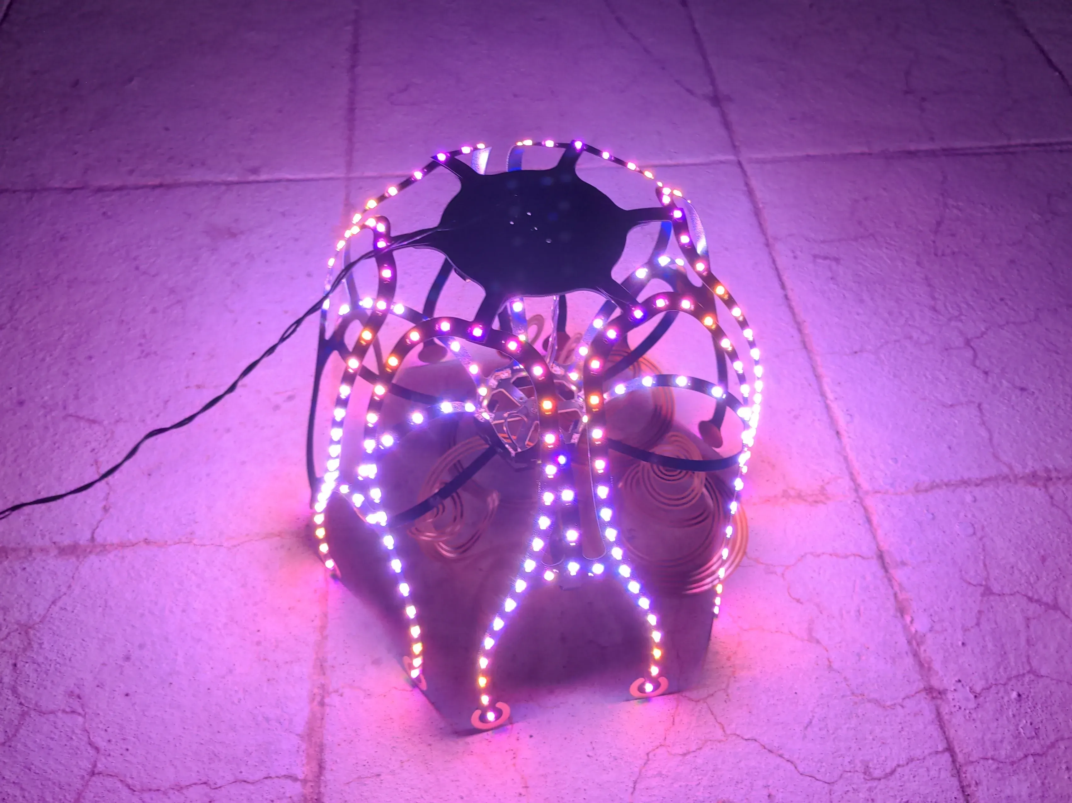
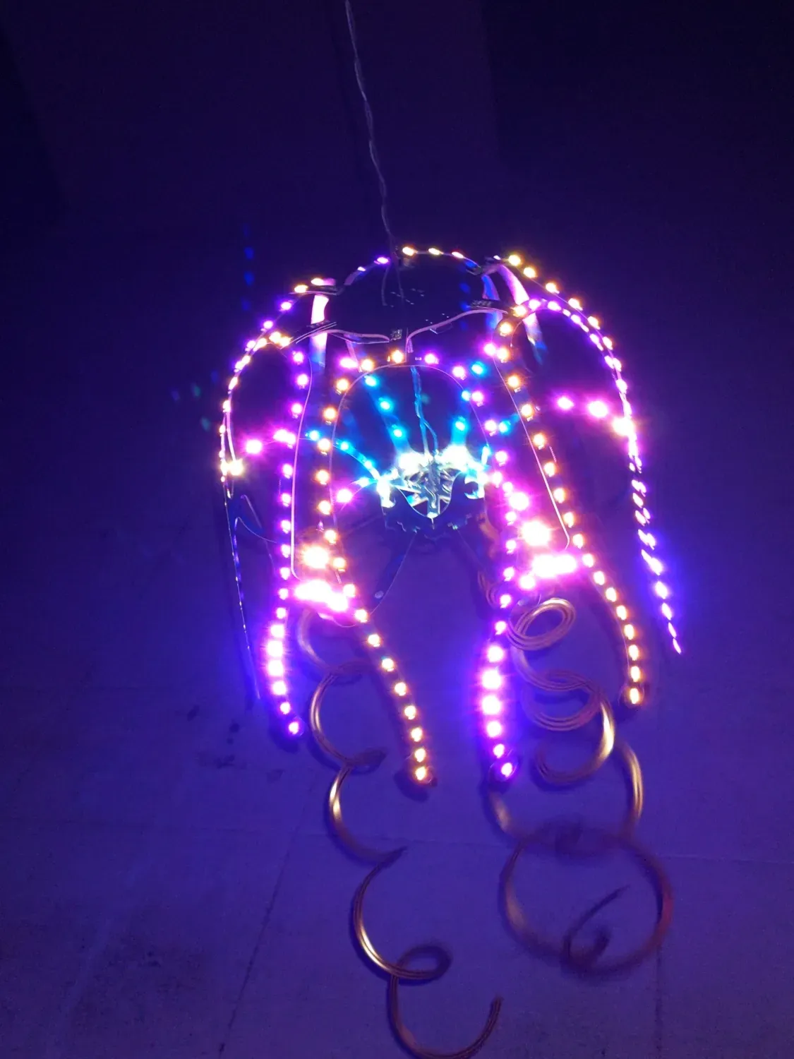
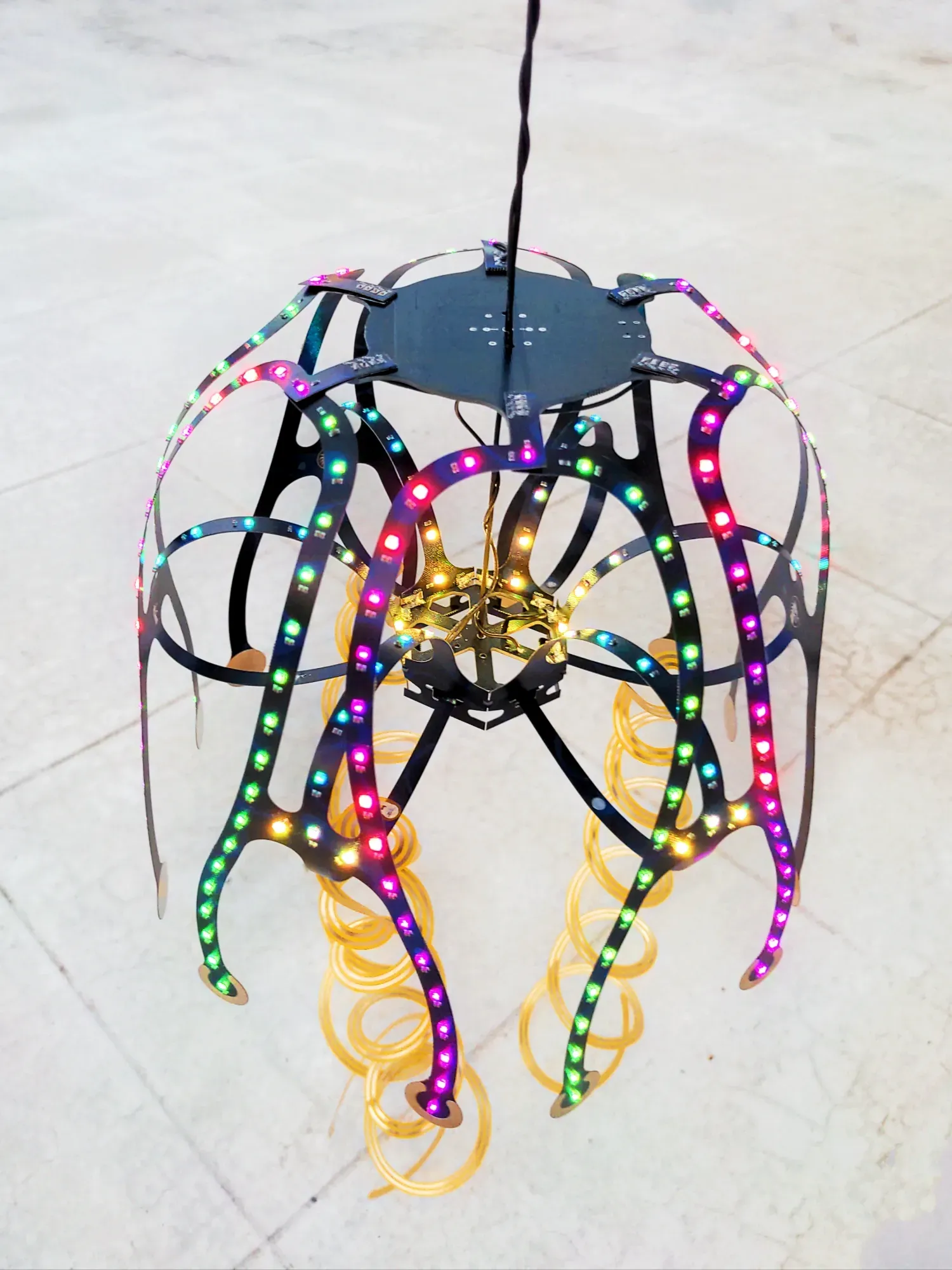
Jelly Fish made with "Rigid" FR4 PCBs
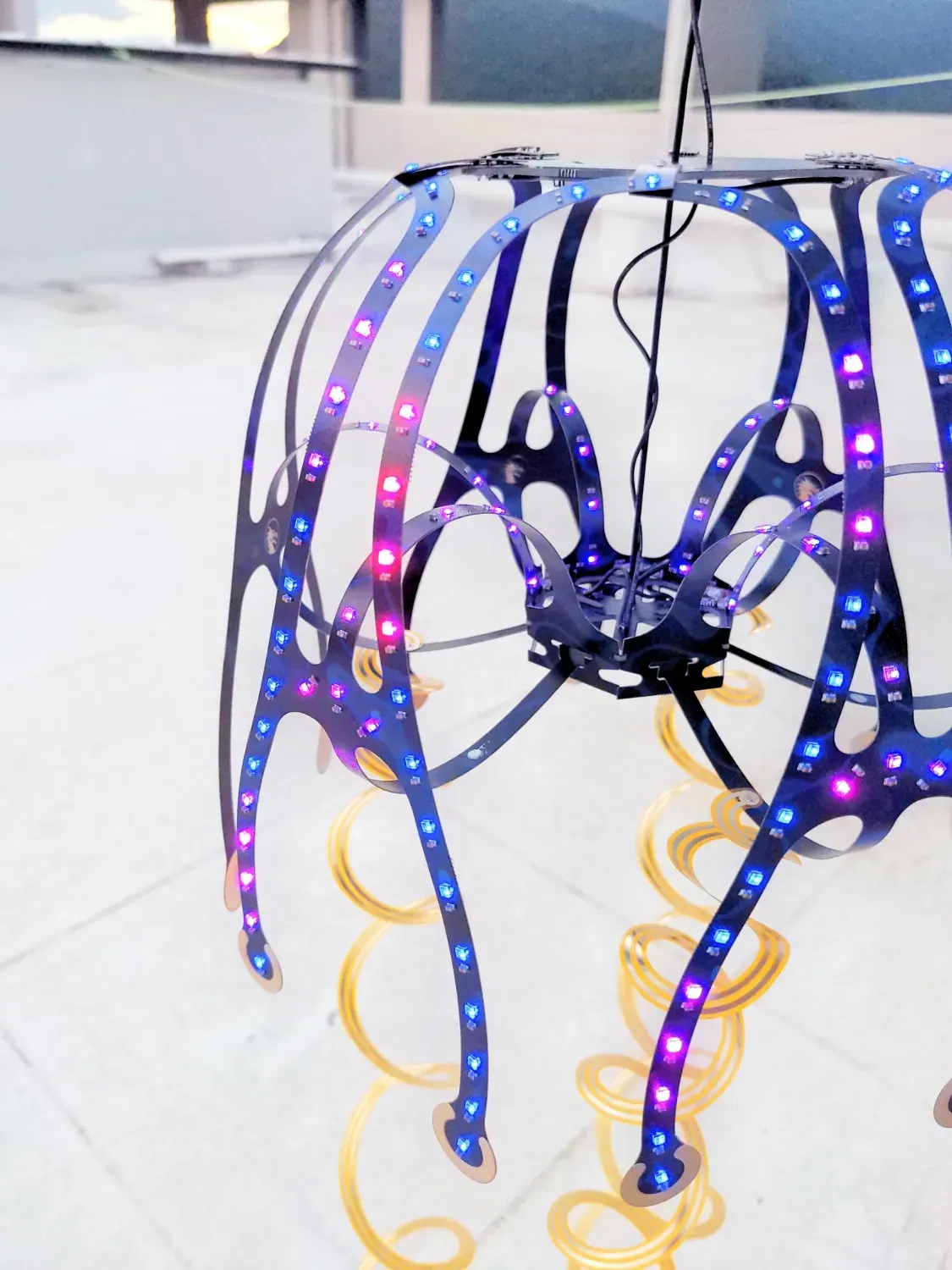
Even rigid PCBs are slightly flexible, this project takes it to the extreme. A three dimensional Jelly Fish structure made only with FR4 PCBs
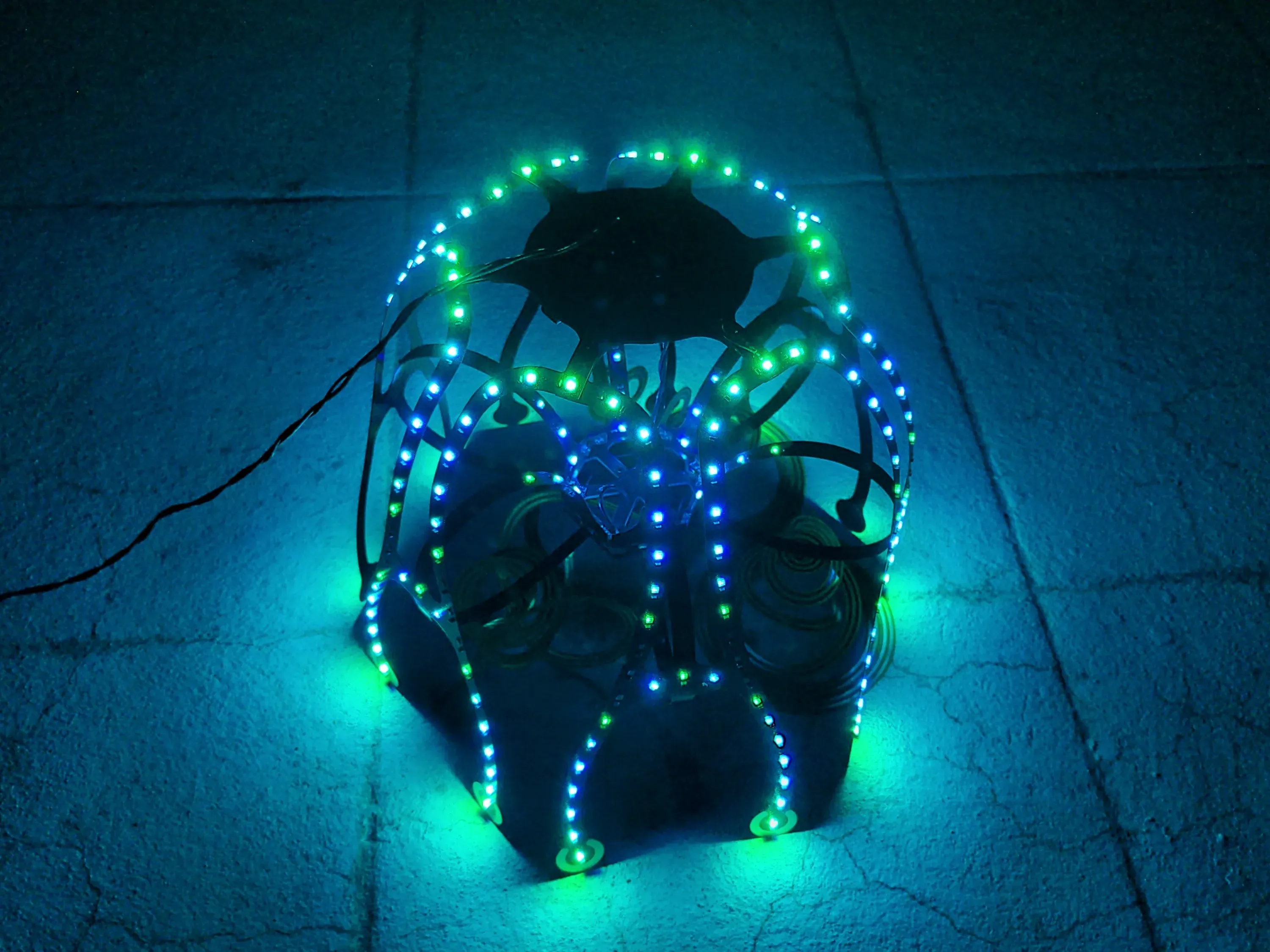
Jelly Fish chilling in the night

Photos
Design Overview:
Sometimes you just have to bend the rules, literally
You would have seen minimum bend radius ratings for flexible pcbs. You wouldn't have seen these ratings for an FR4, its because they are not supposed to be bent. But thats not gonna stop us from doing exactly that
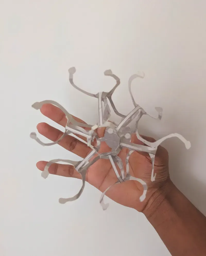
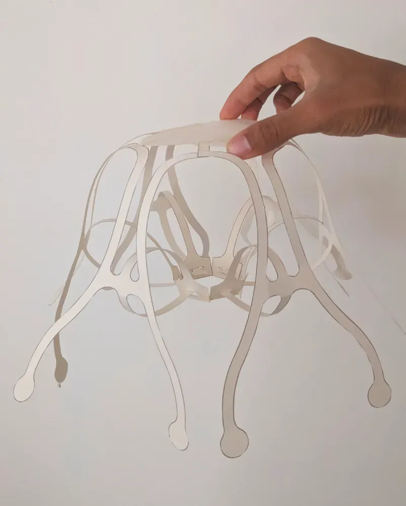
Paper prototypes:
Original design credits to Ben Nagaoka for the Wind Jelly Design.
1) First Mini prototype
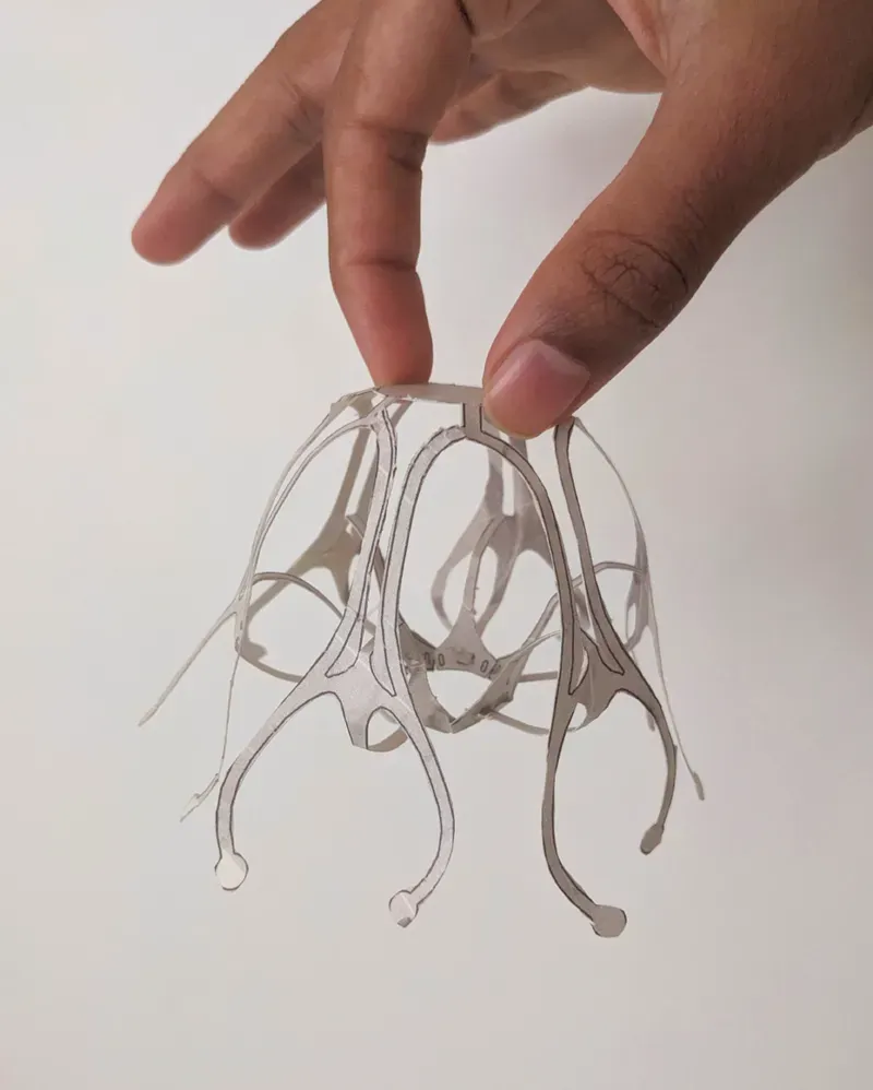
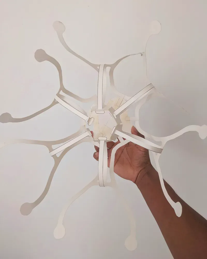
2) Second prototype optimized for PCB fabrication
CAD Drawing in Onshape
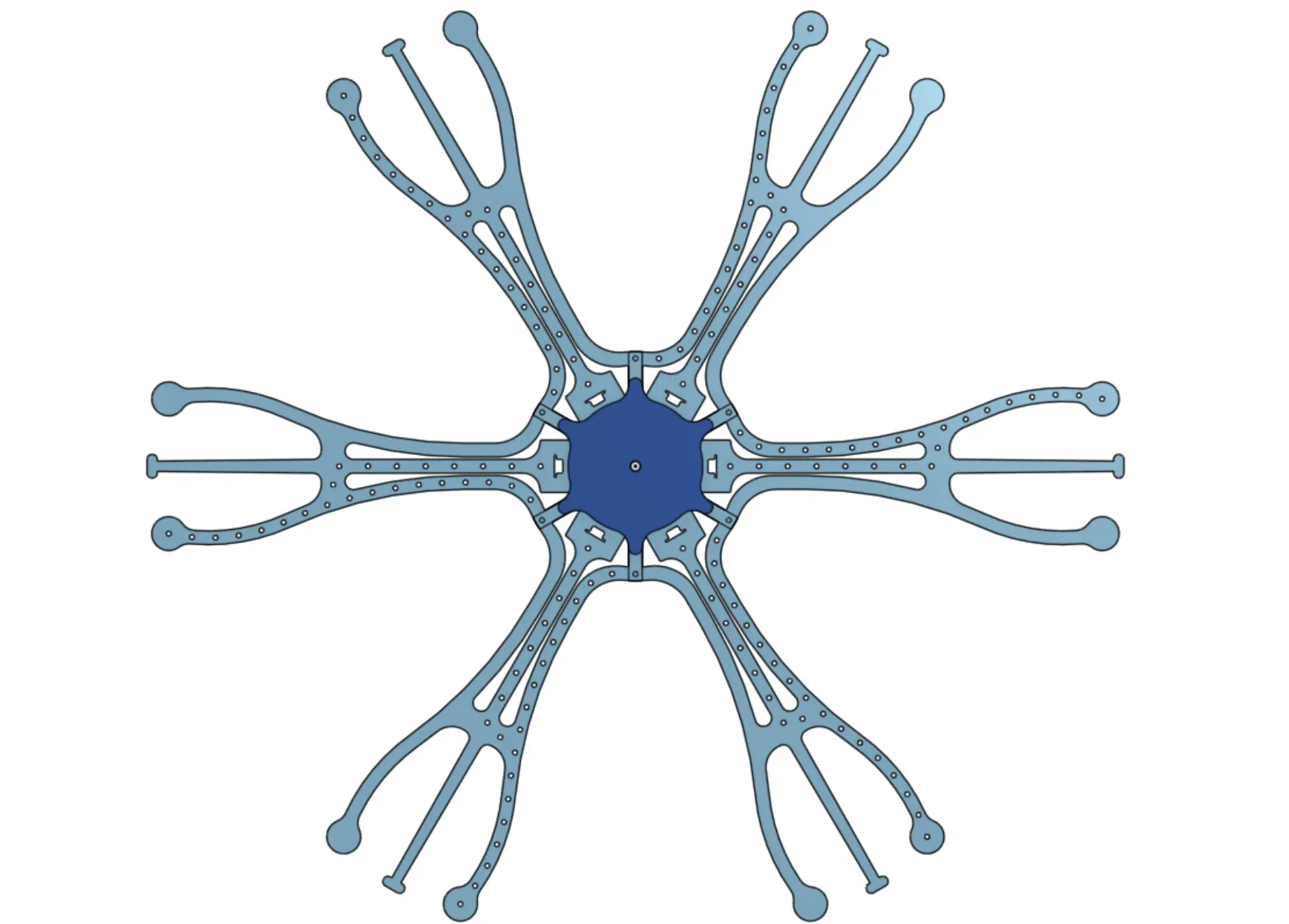
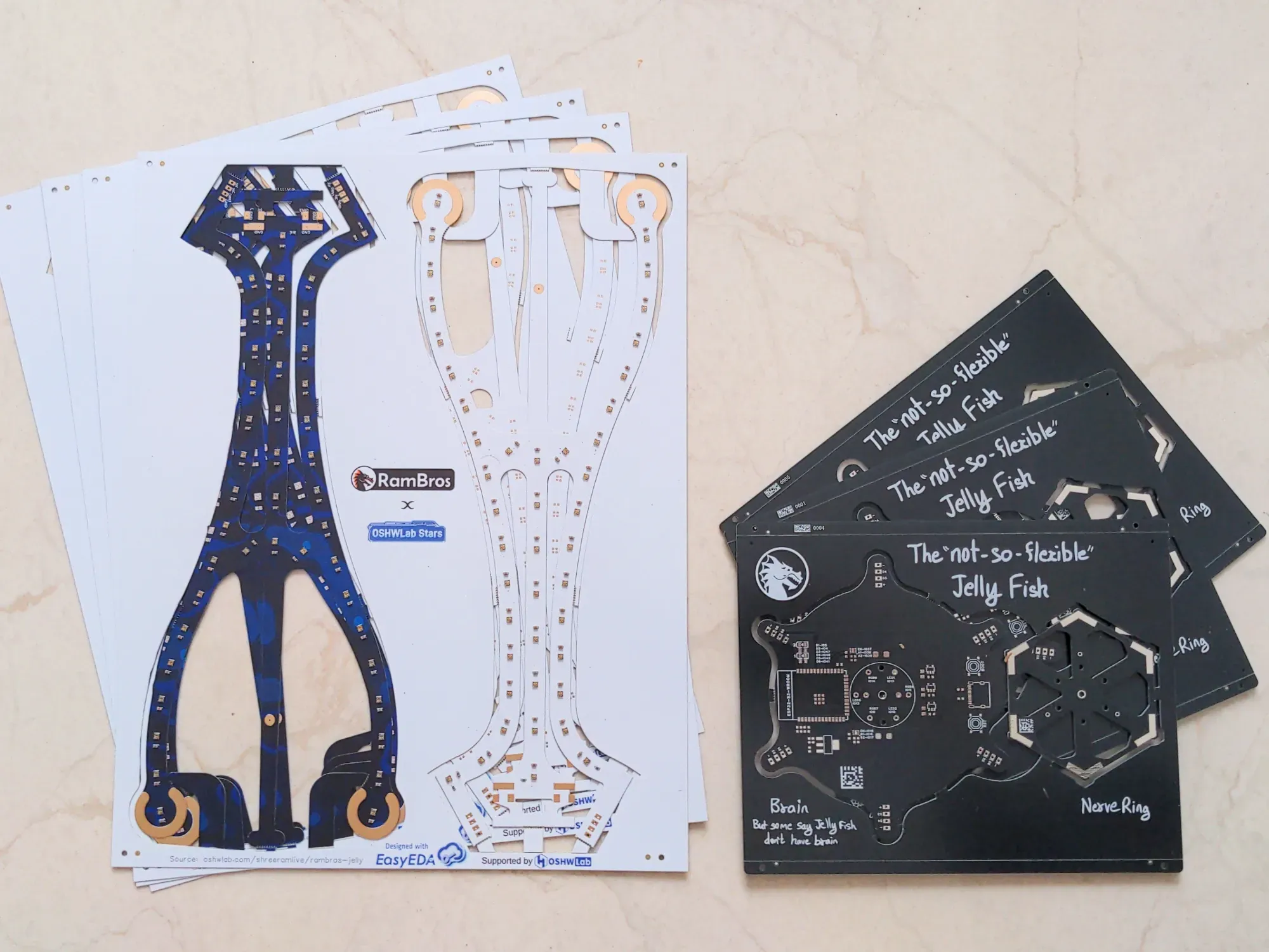
PCB Panels:
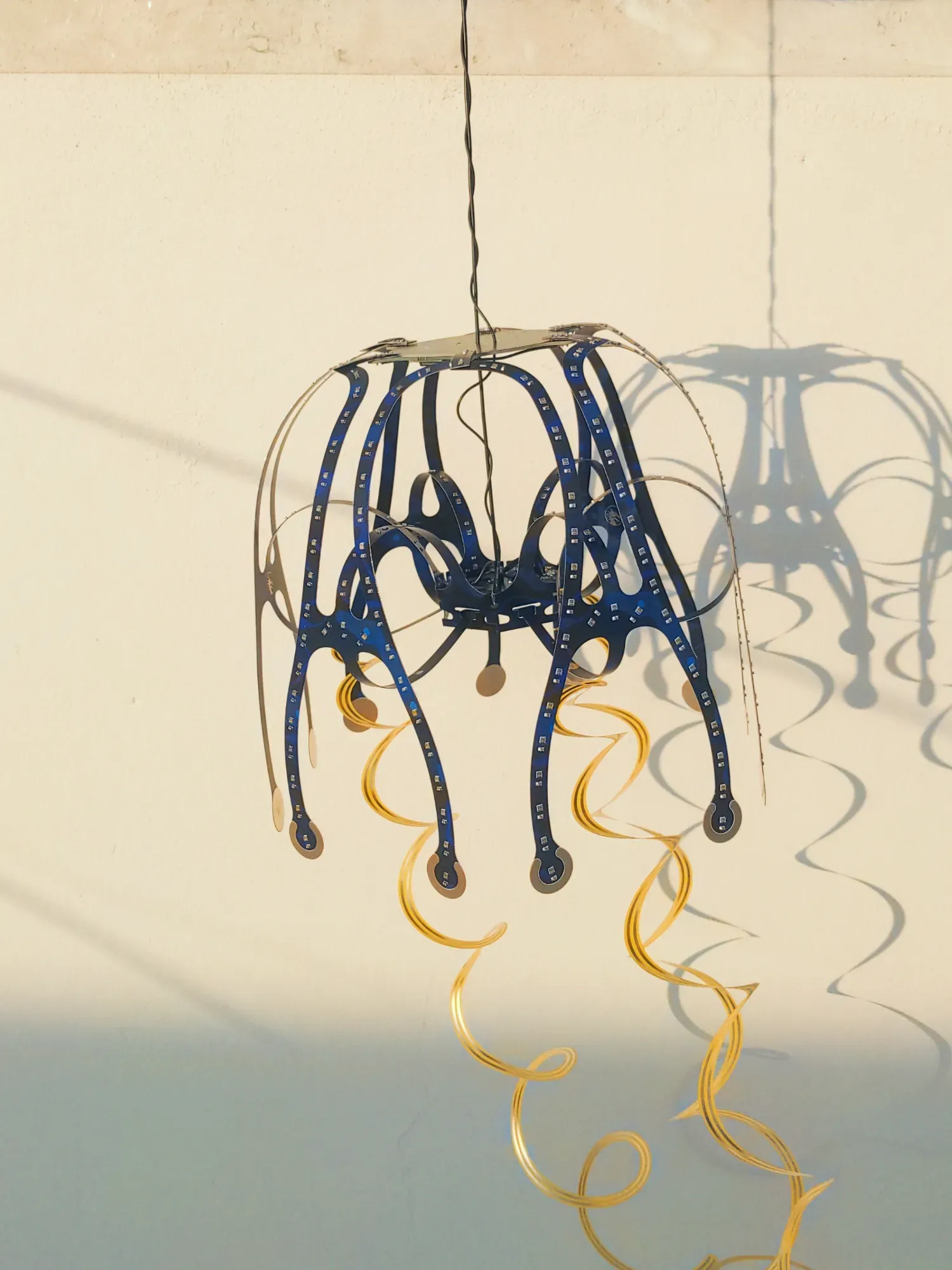
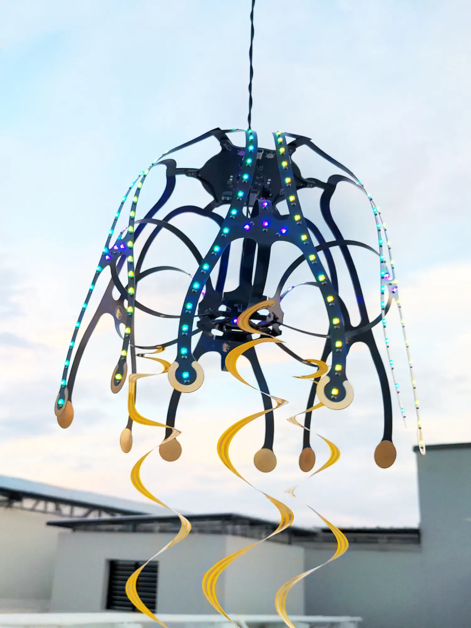
The template was first drawn in onshape and the initial prototypes were made with paper to verify and refine the design. The total diameter of the template would be 590mm. So the Legs and Brain were separated into different panels to optimize for production. And lastly, I added some spiral tentacles using actual polyamide FPC.
- The Leg panel is a 0.4mm Color PCB
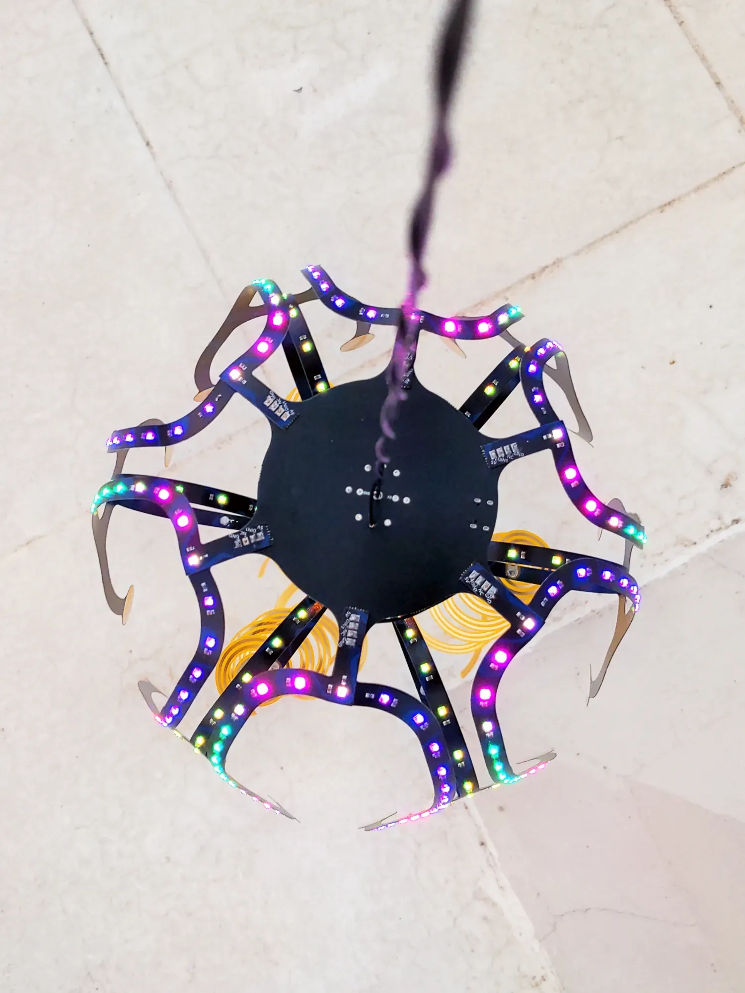
- The Brain panel is standard 1.6mm Black PCB
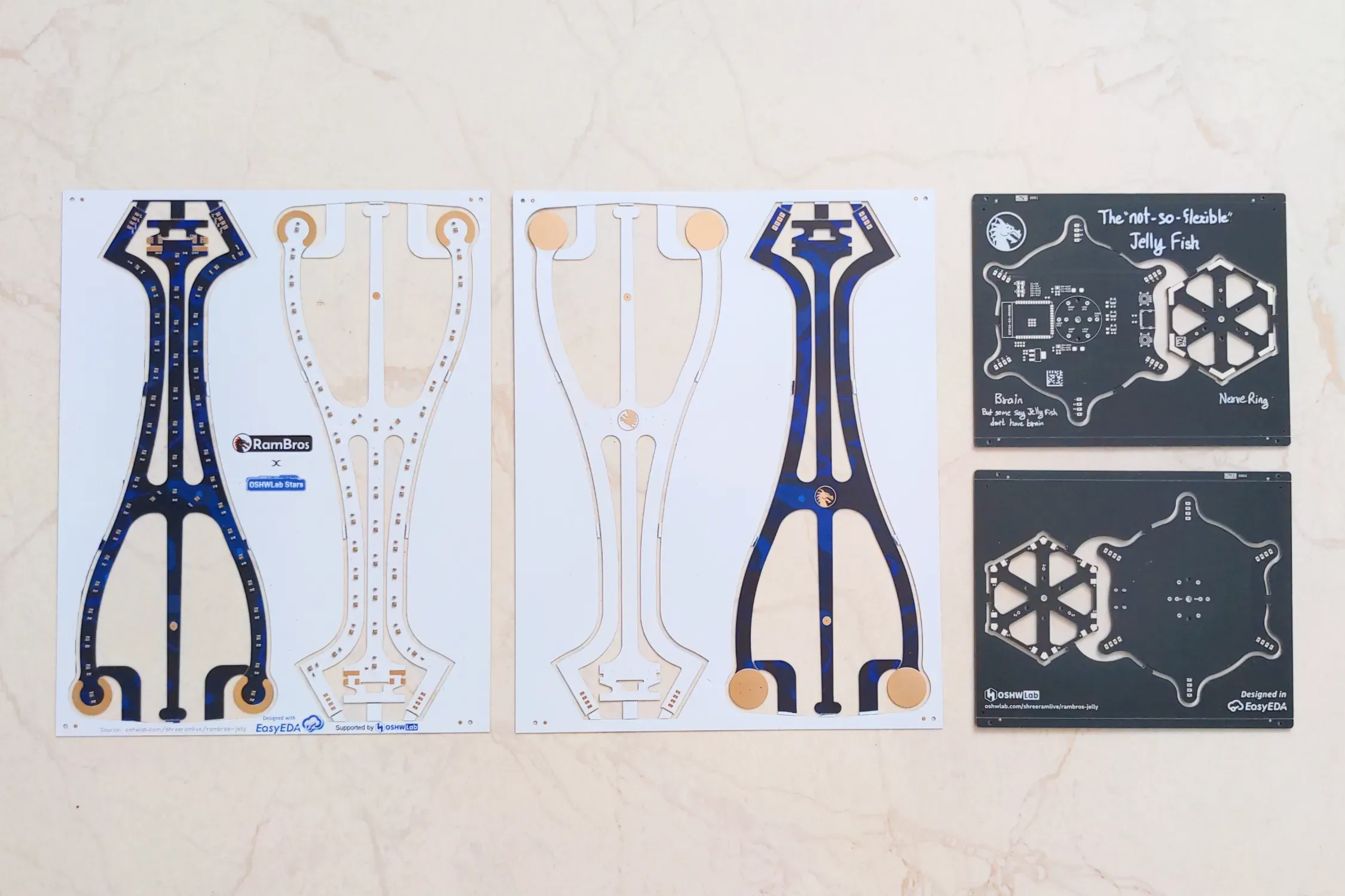
Both boards in the Leg panels should be colorful. But jlc doesnt copy the color silkscreen during panelization, so thats why one of the board in color panel doesnt have any silkscreen. Thankfully I ordered extra pieces for testing, so the project continued smoothly.
Testing:
Firmware:
WLED is used to control the Addressable LEDs. Firmware is flashed via USB with the Wled installer
- Only after receiving the boards, I realized that Wled firmware can drive only 4 strips with ESP32-S3. This board has 9 RGB outputs.
- So as a workaround, I modified the LED connections to use only 3 RGB outputs.
The addressable LEDs are power hungry, This can easily draw more than 5A at full brightness. I have limited the current in firmware to 3000mA since I am using a 5V 3A power adaptor. So the brightness will be automatically modulated to be within the limits of the power supply.
Why bend a FR4 PCB?
- The main reason would be the production cost. FR4 Boards are much more cost effective compared to flexible technologies (2x-10x).
- For products which require only slight bends and no repeated bending, this is a potential alternative. more info
If you stay within the elastic deformation of the FR4 then there's no issue. Even after the product is assembled, the PCB will slowly creep to the deformed shape over a period of time.
FR4 is a composite made up of glass strands binded with resin; It is the most commonly used material for PCB due to its good mechanical and thermal properties. Glass is a bendable material, thats why its used in fiber optic cables. The FR4 composite is much more durable, so it can bend even more compared to the glass of same thickness.
The rigidity increases as the board thickness increases. In jlcpcb, the minimum FR4 board thickness is 0.4mm for 2 layer boards. So we have used that in this project.
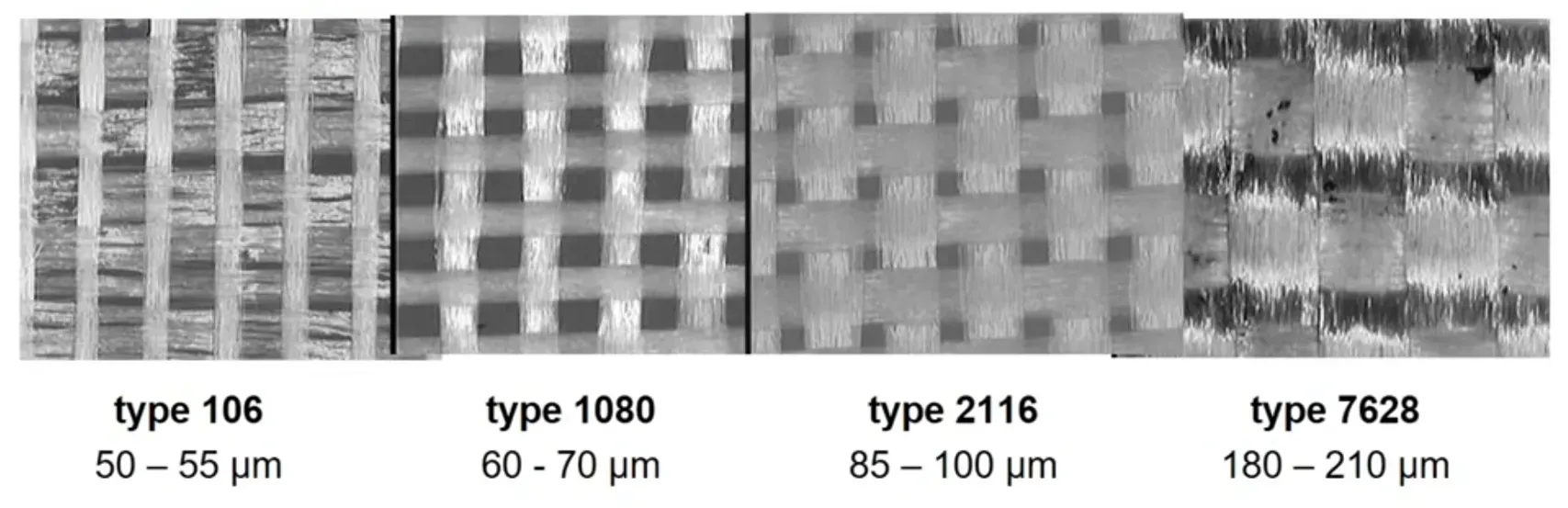
source: wurth electronik
Limitations:
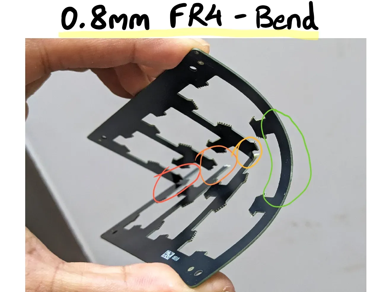
- FR4 can bend slightly, but they can crack and snap if we make a sharp bend.
- With repeated bending, The copper traces can cut off and the copper fills can crack.
- SMD components on the bend area can be problematic; More prone to loose joints.
Project Origins:
I recently got interested in flexible technologies such as FPC, Rigid-flex and Semi-flex especially with the launch of Transparent FPC by jlcpcb. Speaking of transparent things, the first idea that popped into my head was jelly fish.
While I was planning this project, a thought crossed my mind - why not make the flexible parts with the FR4 itself? and thats how this project started.
References:

- This project's PCB and PCBA service was sponsored by the OSHWLAB Stars campaign.
- Prototype was completed in September 2025.
Design Drawing
BOM
 Clone
CloneProject Members
 Empty
Empty
Comment