

 Ongoing
RPI Pico ESP-01
STDRPI Pico ESP-01
License
:CC-BY 3.0
Description
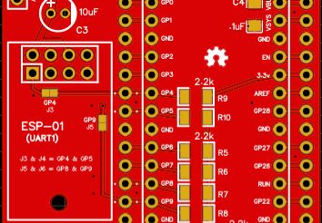
RPI Pico ESP-01 breakout board
It includes a place for an ESP-01 module, power for the Pico and ESP, or an option for separate power for each.
The ESP is connected to UART1 (Serial2 for Arduino) RX/TX pins. There are also optional pullup resistor locations for the I2C bus.
Solder J1 close if only using the onboard regulator, and make that an 1117 LDO 3.3v 1a type. If powering the modules separately, keep J1 open and supply 3.3v to the ESP via the Ext. header. If this option is chosen, an 1117 LDO 5V 1a regulator can be used or the 3.3v version.
J2 is for bypassing the diode if you wish to not use one.
J3 & J4 = GP4 & GP5
J5 & J6 = GP8 & GP9
The PCB can be easily made at the PCB house of your choice.
The Gerber files can be found at https://github.com/jscottb/pcbs along with others I have.
Design Drawing
BOM
 Clone
CloneProject Members
 Empty
Empty
Comment