

 Ongoing
Sensor Monitoring Using LoRa & Arduino
STDSensor Monitoring Using LoRa & Arduino
548
0
0
0
Mode:Full
License
:GPL 3.0
Creation time:2022-09-07 06:15:00Update time:2022-09-07 06:15:29
Description
There are various sensor monitoring methods are available some of them using IoT and others using offline protocols like Bluetooth and BLE. But the offline method doesn’t offer a good range and online methods are expensive and very compilated. Today, we are going to make a simple sensor monitoring system using LoRa (long range radio). LoRa supports a very long range of 7-10 miles and data can be transferred without internet. It is quite similar to walkie talkie.
This article is brought to you by JLCPCB- PCB manufacturer from CHINA offers 5pcs of 2layer PCB boards just in $2.
LoRa:
LoRa is a radio modulation technique that is essentially a way of manipulating radio waves to encode information using a chirped (chirp spread spectrum technology), multi-symbol format. LoRa as a term can also refer to the systems that support this modulation technique or the communication network that IoT applications use.
The main advantages of LoRa are its long-range capability and its affordability. A typical use case for LoRa is in smart cities, where low-powered and inexpensive internet of things devices (typically sensors or monitors) spread across a large area send small packets of data sporadically to a central administrator.
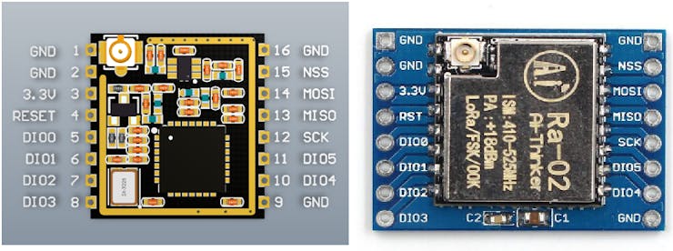
LoRa work on different frequencies and different modules are available for different country. You can see the Wikipedia article to know more about more advance protocols over LoRa like LORAWAN and alliance. I am using LORA RA01 module from Ai thinker on 433MHz frequency.
433E6 for Asia
868E6 for Europe/Africa
915E6 for North America
Components used:
LoRa RA01 module
Arduino Nano
Jumper wires
DHT11 sensor
5v power supply
USB and programmer
Custom PCB from JLCPCB
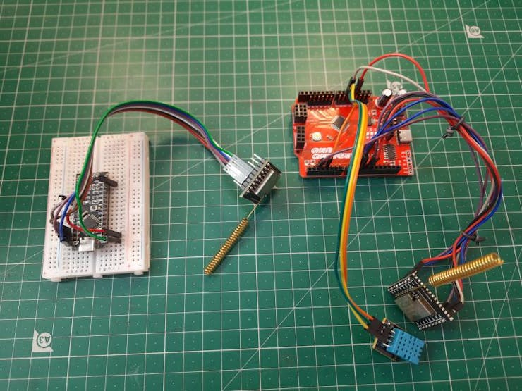
Circuit diagram:
Because my Lora module RA01 works on SPI interface so an external library is used for the communication. Here MOSI, MISO and SCK pins are connected to D11, 12 and 13 respectively. For reset we are using D9 and D10 NSS(Enable). No need to define these pins in code because these are default with the Lora library. D0 of the Lora is connected to D2 of the Arduino. LoRa works on 3.3volts, 5v can damage the entire setup.
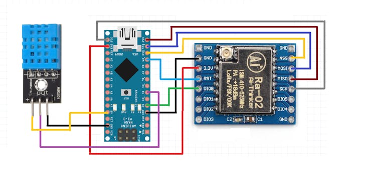
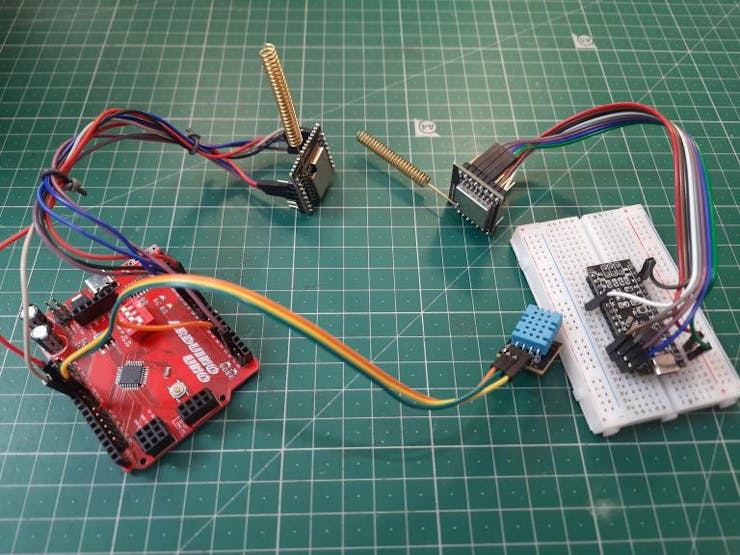
DHT11 sensor is connected to the transmitter which reads the data. Any blank digital pin can be assigned for DHT. Then Arduino process that and make a string of that data to send to the receiver. the connections for the lora are same on both receiver and transmitter end. I am using Arduino nano for the receiver and UNO for the transmitter only for demonstration purpose.
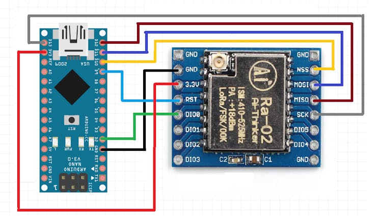
The receiver connections are also same and instead of any external screen we are using Arduino IDE serial monitor to display the values. We can use one receiver for many devices just change the to change the address, but this is the topic for another article.
PCB layouts:
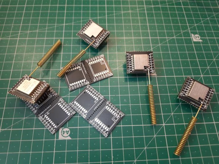
I using my own made Arduino in this project, you can see the full building instructions from here. JLCPCB is offering PCB SMT assembly services just from $8 and $2 for PCB prototyping service. I got this LoRa breadboard compatible modules from JLCPCB assembly service.
Just upload you Gerber file along with BOM and CPL for SMT order. Sign-up using this link and get a huge discount coupons of worth $54. To know more about the services, visit JLCPCB. If you want to make the same project as mine then download all the required files from here.
Code:
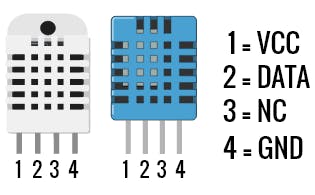
The DHT 11 and DHT22 comes with the same pinout, premade module has some pin variations. So keep the pin description in mind before connection. You can also change the sensor type in the transmitter code give below.
Transmitter code:
1) Initialize with pins, libraries and sensor type, counter is to display the string data value:
#include <SPI.h> #include <LoRa.h> #include <DHT.h> #define DHTPIN 4 // what digital pin we're connected to #define DHTTYPE DHT11 // select dht type as DHT 11 or DHT22 DHT dht(DHTPIN, DHTTYPE); int counter = 0;
2) begin the serial monitor and lora initialization and set the channel/ radio power output:
void setup() { Serial.begin(9600); while (!Serial); Serial.println("LoRa Sender"); dht.begin(); //initialise DHT11 if (!LoRa.begin(433E6)) { Serial.println("Starting LoRa failed!"); while (1); } LoRa.setSyncWord(0xF3); LoRa.setTxPower(20); }
3) Store the value of temperature and humidity using a float number function and return if there is any problem in DHT sensor:
float h = dht.readHumidity(); float t = dht.readTemperature(); if (isnan(h) || isnan(t)) { Serial.println(F("Failed to read from DHT sensor!")); return;
4) Lora will send the data packet with increase in counter every time with string data values of temperature and humidity:
Serial.print("Sending packet: "); Serial.println(counter); // send packet LoRa.beginPacket(); LoRa.print("Data:"); LoRa.print(counter); LoRa.print("> "); LoRa.print("Temperature: "); LoRa.print(t); LoRa.print(" "); LoRa.print("humidity"); LoRa.print(h);
5) End the packet info, increase the counter and repeat the code after a delay:
LoRa.endPacket(); counter++; delay(5000);
Receiver code:
1) Initialize the libraries and begin the serial monitor:
#include <SPI.h> #include <LoRa.h> void setup() { //initialize Serial Monitor Serial.begin(9600); while (!Serial); Serial.println("LoRa Receiver");
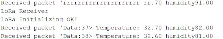
2) Receive lora data packages and display them on serial monitor:
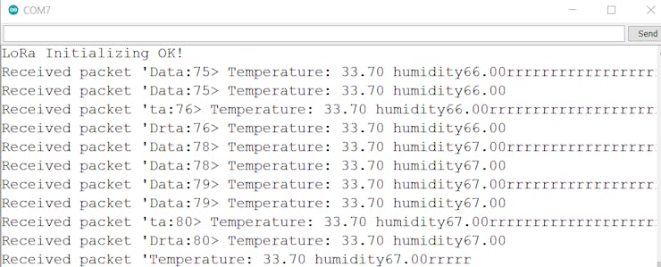
String LoRaData; int packetSize = LoRa.parsePacket(); if (packetSize) { // received a packet Serial.print("Received packet '"); // read packet while (LoRa.available()) { LoRaData = LoRa.readString(); Serial.println(LoRaData); }
Libraries used:
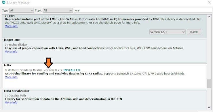
Here I am using LoRa library by Sandeep Mistry, it is very well optimized library for SPI protocol LoRa modules. You can also see more examples and go through each of them in order to make some new projects.
Project working:
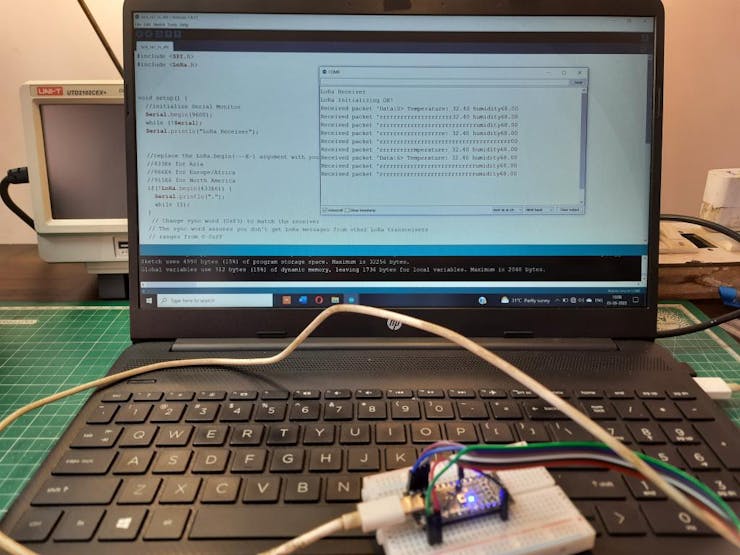
In this way you can read any data from sensor, the data is just a value that can be send over air to long distances using string functions in LoRa. Now sometimes the received data is just mistitled because of voltage fluctuations and noise. But you can add an external capacitor between power lines and reset the microcontroller which can solve this problem.
So, now it is your time to build a project using long range radio protocol and let me know in comment section. Get me on Instagram Sagar_saini_7294.
Design Drawing
BOM
 Clone
CloneAdd to Album
0
0
Share
Report
Project Members
Followers0|Likes0
Related projects
 Empty
Empty
Comment