

 Ongoing
NTC v/s PTC Main Difference And Applications
STDNTC v/s PTC Main Difference And Applications
457
0
0
0
Mode:Full
License
:GPL 3.0
Creation time:2022-08-07 10:39:53Update time:2022-08-07 10:43:46
Description
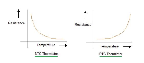
NTC and PTC are known as thermistors, which can be further known as temperature-controlled resistance. Now something is related to resistance but how it works and which type of circuits can be designed using these components. Let’s know the working concept and then we will use them practically.
The value of these thermistors is not linearly change with the temperature. The manner in which the resistance of a thermistor decreases is related to a constant known in the thermistor industry as beta (β). Given by:
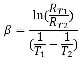
Where: Rt1 = Resistance at Temperature 1 Rt2 = Resistance at Temperature 2 T1 = Temperature 1 (K) T2= Temperature 2 in (K)
NTC (Negative temperature Coefficient):
An NTC thermistor is a temperature sensor that uses the resistance properties of ceramic/metal composites to measure the temperature. Our full spectrum NTC sensors offer many advantages in temperature sensing including miniature size, excellent long-term stability, high accuracy and precision.

This project is sponsored by JLCPCB, one of the leading PCB manufacturer form china. JLCPCB provides the good quality FR4 2layer PCB in just $2 for 5pcs. To know more about the services like PCBA, STENCIL making and 3D-printing then visit JLCPCB now. Sign-up using this link and get free coupons of worth $54 to place the order.
PTC (Positive Temperature Coefficient):
PTC thermistors are resistors with a positive temperature coefficient, which means that the resistance increases with increasing temperature. PTC thermistors are divided into two groups based on the materials used, their structure, and the manufacturing process. A PTC thermistor is a thermally sensitive resistor used in a circuit for its protection. A PTC fuse is used to protect electronic devices when heat or excessive current is produced.
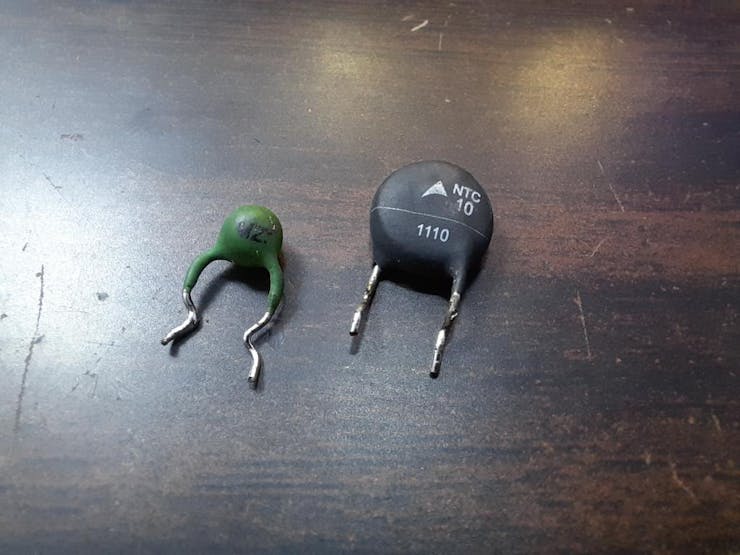
Heating and cooling test of both thermistors:
Let’s now see how the resistance actually varies with increase/ decrease in temperature. We can directly put them on fire but keeping the safe side I am using my soldering iron and ICE for these two tests here.
For the NTC the value of resistance goes down as it comes in the contact of heated soldering iron and increase rapidly when tested with ICE.
The same thing should be featured by PTC but in reverse. But the particle approach is something different. The resistance increases on heating but remains constant when tested in colder region. That’s why the NTC is preferred to use a temperature monitoring device. We can use PTC as a reusable fuse. The proper demonstration about fuse action is given below.
Working of PTC:
As we know resistance increase on heating, and PTC got heated if the excessive current flow through it. Which cuts the power connection, here I connected an LED in series with PTC and after heating a little bit the resistance goes up and thus turn off the LED.
But after some time, the LED start glowing again, when temperature comes down. This is what makes PTC a reusable fuse. Other type of fuses is only one-time devices but in modern electronics systems PTCs are used in the place of fuses.
Working of NTC as a temperature monitoring device:
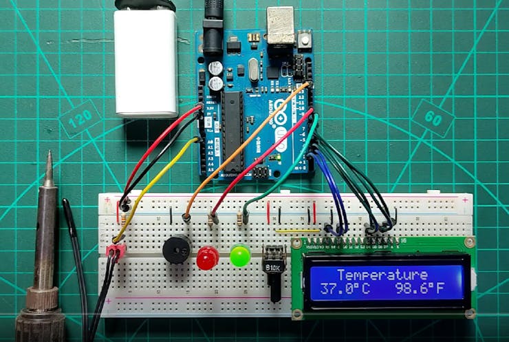
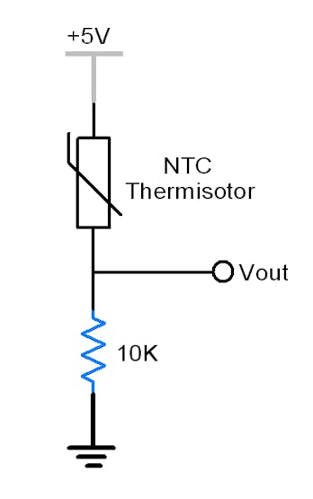
The value of NTC is not linear with temperature, it gives a logarithmic curve as stated above. Which is modified in the Arduino code. Here we are using a 10k NTC in voltage divider configuration with a 10k resistor.
Components required:
1) NTC 10K
2) 10K resistor
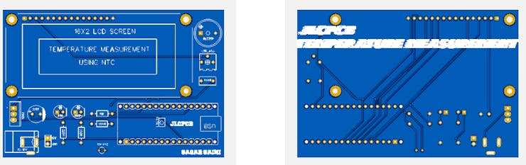
3) 16X2 LCD
4) Arduino
5) 10k potentiometer
6) LEDs, buzzer and connecting wires
7) Custom PCB.
Circuit diagram:
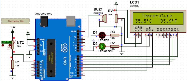
In the circuit, when the temperature reaches high the red led glow with buzzer. Green led is the indication of normal temperature. Temperature values in celsius and fahrenheit are available on screen. 10K Potentiometer is used to adjust screen contrast.
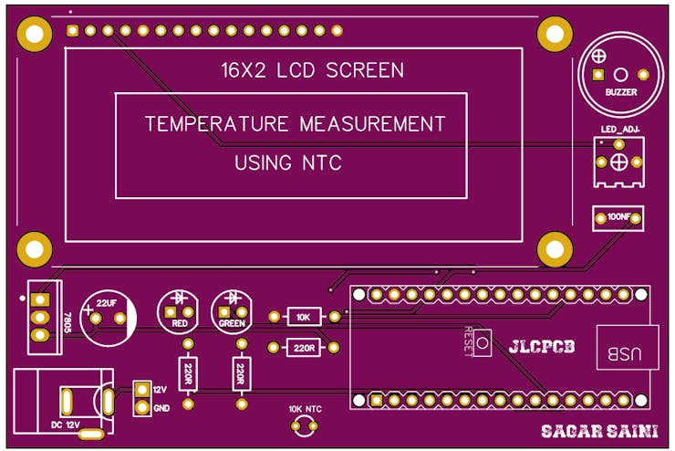
PCB FILES:
Then I designed the designed the schematics according to the modified schematics in EasyEDA and made the PCB fabrication Gerber files from there.
I am using JLCPCB pcb prototyping, SMT assembly and stencil service since 2020 for my projects. The quality is very high as compared to price, $2 for 5pcs 2layer PCB and SMT assembly starting from $8.
JLCPCB PCB ordering process:

Ordering process is quite simple with the auto PCB detection feature of the JLCPCB software. Download the Gerber file given the description of this project.

Sign-up using this link and get your free coupons.
Upload you Gerber file.
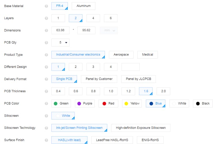
Set all the parameters, quantity, color and finishing.

Design Drawing
BOM
 Clone
CloneAdd to Album
0
0
Share
Report
Project Members
Intellectual Property Statement & Reproduction Instructions
This is an open-source hardware project. All intellectual property rights belong to the creator. The project is shared on the platform for learning, communication, and research only; any commercial use is prohibited. If your intellectual property rights are infringed on EasyEDA, please notify us by submitting relevant materials in accordance with the Rules for Complaints and Appeals of IPR Infringement.
Users must independently verify the circuit design and suitability when replicating this project. All risks and consequences are borne by the user, and the platform assumes no liability.
Followers0|Likes0
Related projects
 Empty
Empty
Comment