

 Ongoing
Esp8266 Shield using SMT assembly
STDEsp8266 Shield using SMT assembly
540
0
0
0
Mode:Full
License
:GPL 3.0
Creation time:2022-07-26 07:44:00Update time:2022-07-26 07:44:46
Description
ESP8266 is very powerful and most preferred microcontroller in IoT. This is used worldwide not only because of the wi-fi compatibilities but also due to open-source network. This comes with 32bit microcontroller running at 80Mhz. But it can be overclocked to 160Mhz keeping cooling conditions in mind. ESP8266 is designed on a very small PCB with real chip of EX8266 having external SPI flash memory.
ESP8266 comes with 2.0mm hole spacing and can’t be soldered directly with headers available in market. To work with this microcontroller, we have to buy the development boards which cost double. Some compatible programming shields are also available but usually out of stock at some places. That’s why I will make my own shield which can be programmed easily and can be used with breadboard for other projects.
ESP8266 specs:

· CPU: Tensilica Diamond Standard 106Micro (aka. L106) @ 80 MHz (default) or 160 MHz
· Memory: 32 KiB instruction, 80 KiB user data
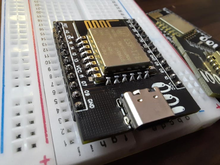
Esp8266 shield:
I build a ESP8266 SHIELD keeping breadboard compatibilities with easy programming in mind. AMS1117 3.3v voltage regulator is there to power up the ESP8266 MCU that works at 3.3v DC. A 10k resistor is connected between enable and VCC pin to make it logic 1 when programming. GPIO 15 is pulled down with an another 10k resistor. A USB type C female jack is connected to power up the microcontroller.
Programming:
Because this is a stand-alone shield having only microcontroller, it doesn’t support programming directly through USB. TO program the shield either you need an external programmer or a Nodemcu development board. See how to program the ESP8266 from here. We will build a dedicated programmer board for this shield that can be directly plugged to it with the help of pin headers.
JLCPCB Assembled boards:
Esp8266 microcontroller is very cheap and I need a lot of them for home automation and project making. I tried JLCPCB SMT assembly service which costs me just $8 for assembling and soldering.
The assembled boards are really outstanding, all the components used are original and soldered properly on place. JLCPCB has just launched an another PCBA service which supports dual side components assembly. Visit JLCPCB from here and explore all the service offered by them.
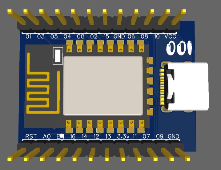
PCB specs:
I designed the circuit schematics in EasyEDA and then export all the required files for PCB assembly service. It is a double layer PCB with HASL finishing and 1.6mm thickness.
If you want to use the same designs as mine then download them from here. Try JLCPCB SMT assembly service and get free coupons of worth $54 on first sign-up.
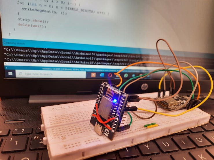
Working:
I upload first program to test the neo pixel led 7 segment display. And this microcontroller is working very fine with this. You can access all the functions of the MCU and it’s better to order it from JLCPCB Assembled service.
You can see some cross connection in the above displayed GIF is because I forget to connect the tracks of VCC to voltage regulator but fixed in the Gerber file provided for download. You can also cross check the connection from the circuit diagram file given below.
How to order SMT assembled PCB:
1) Collect all the material like Gerber files, BOM file and pick and place (CPL) file.

3) Go to Coupons section and check the eligible coupons.

4) Upload your Gerber file and select all the parameters.
5) Then mark on SMT assembly and upload BOM/ CPL file.
6) Choose the components for assembly.
7) Add to cart and go for checkout.
8) Fill all the details for delivery and select your delivery method.
9) Make the payment and get your PCB in just 7 days.
Design Drawing
BOM
 Clone
CloneAdd to Album
0
0
Share
Report
Project Members
Followers0|Likes0
Related projects
 Empty
Empty
Comment