

 Ongoing
Big RGB Stripe making using SMT Service
STDBig RGB Stripe making using SMT Service
310
0
0
0
Mode:Full
License
:GPL 3.0
Creation time:2022-08-24 18:40:09Update time:2022-08-24 18:40:53
Description
I need a big RGB stripe for my gaming room, so that I can stick that on my setup. But I need one with better durability and brighter LEDs with Good heat dissipation. The WS2812 RGB neo pixels may do the fine job but these strips come with flex PCB. Which I would not recommend for high brightness. Because these neo pixel may produce heat over time and burn the tracks on PCB. I am very addicted to gaming once started I did not know when to end. By the way, you can download all the PCB files from here.
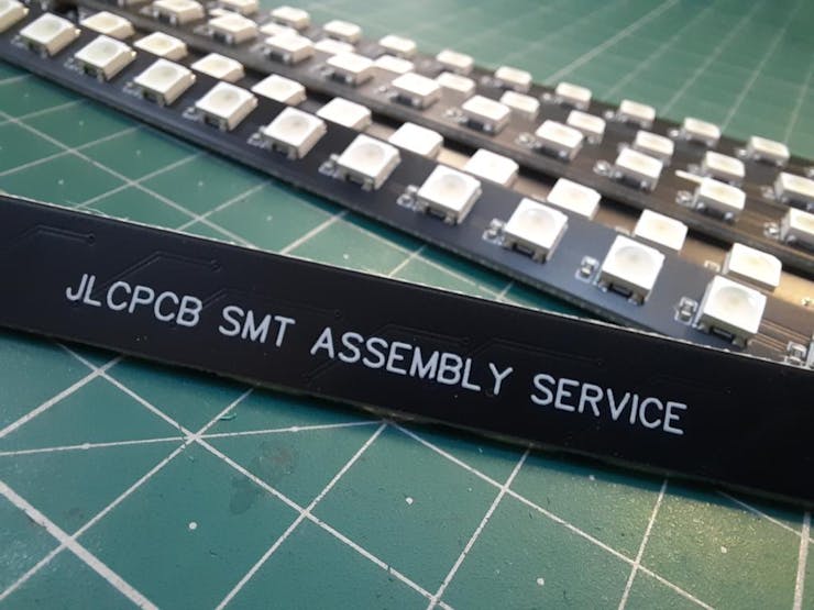
But lets now focus on the main topic, I want to build one Led strip which is hard, comes with desirable design and aluminum material for heat dissipation. The only reliable solution I can found on internet is to go with JLCPCB SMT assembly service.
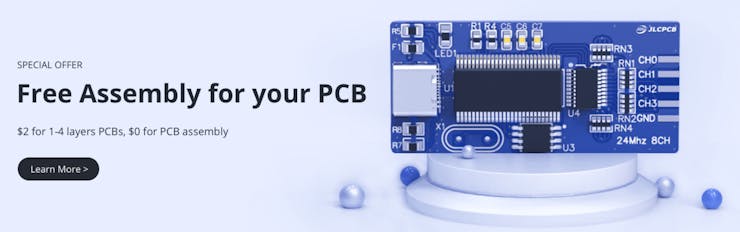
Which can solder all the components for me in a very low price. JLCPCB is the best method to save time along with efforts. Checkout the services now, SMT assembly starting from $8.
Neo pixel Led:
I choose a diffused type LED to make this because brightness is not the only priority. The effects of RGB and over contrast is neutralized by the diffuser itself. Which not only give a better look in short range but also look beautiful in long range. It will not affect the eyes directly with over brightness. Well, you can also control these addressable led as per pixel.
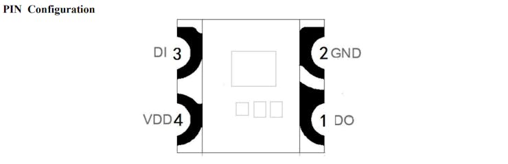
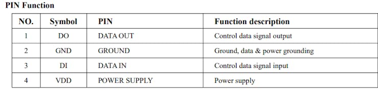
I am using WS2812-5050D led, which has a small controlling chip inside. This led has 4 terminals, two for power and 2 for data. We can connect a number of LED’s in series to make projects like, RGB scrolling text and for other animation projects.
Features:
-
Voltage: 3.3-4.5v
-
16mA operating current per channel.
-
Control circuit and RGB chip are integrated
-
Built-in electric reset circuit and power lost reset circuit.
-
The color of the light is highly consistent, cost-effective.
Circuit diagram:
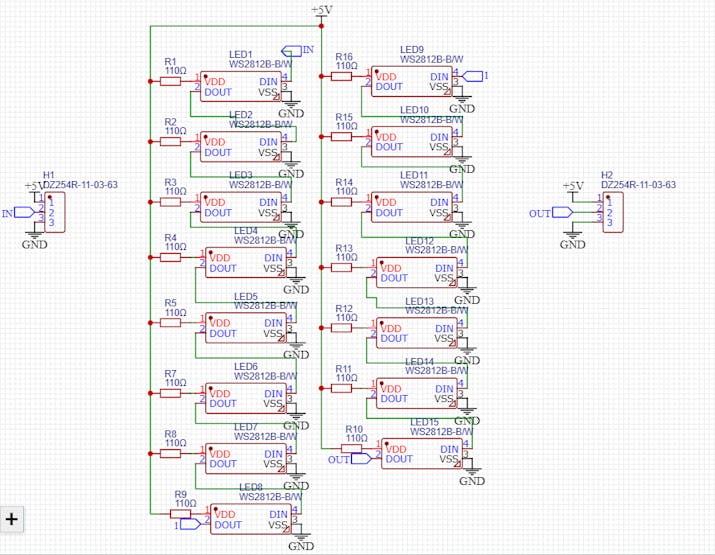
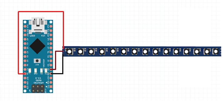
I made the circuit so that per PCB has a total of 15 LED’s and we can connect more PCB in series with the given input/output connection. Arduino is required to set the color, effect and brightness. No need of external power regulator IC because Arduino has 5volt Ams1117 regulator which can support up to 1ampere of current. The connection circuit with Arduino NANO is given below.
Components required:
1) Arduino NANO
2) Ws2812 LED stripe
3) 5v power supply
Design and production:
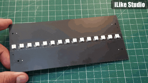
JLCPCB SMT assembly support a minimum of 10mm thickness, so I maintained the width to 10mm and then place 15 LED’s along with current limiting resistor of 100ohms. Then I located the connecting points to the back layer of PCB.
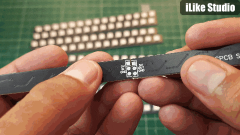
Each PCB has two connecting points one for the input and other for the output. To minimize the soldering gap I choose very end point, so that no wires are required for the connection.
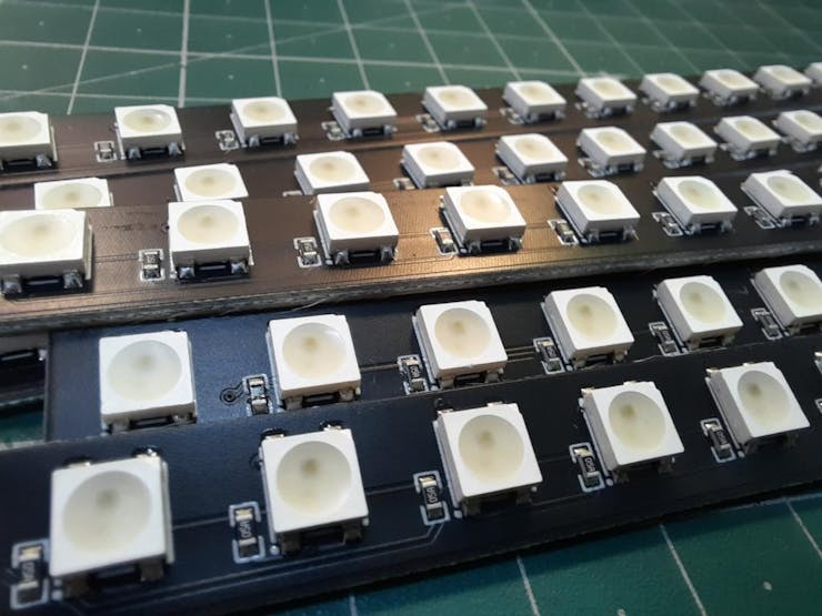
Soldering and SMT assembly:

I choose the SMT assembly because I don’t want to spend my time to solder these panels. The SMD LEDS are very hard to mount and need proper tools. Small increase in soldering temperature or excessive heat may damage the LEDs forever.
Service experience and components:
Because I had chosen protecting side grills to protect my PCB during shipment, they arrived very well. Then I breakout the side panels, all the PCBs are in working condition and soldering and assembling service is great in such a low price. Try SMT assembly service starting from $8. Sign-up to JLCPCB to get free coupons of worth $54 now.
Code:
This code is set for the purpose of a RGB slowed effect, you can change some loop values to make it more usual.
#include <Adafruit_NeoPixel.h> #ifdef __AVR__ #include <avr/power.h> // Required for 16 MHz Adafruit Trinket #endif // Which pin on the Arduino is connected to the NeoPixels? #define LED_PIN 2 // How many NeoPixels are attached to the Arduino? #define LED_COUNT 60 Adafruit_NeoPixel strip(LED_COUNT, LED_PIN, NEO_GRB + NEO_KHZ800); void setup() { #if defined(__AVR_ATtiny85__) && (F_CPU == 16000000) clock_prescale_set(clock_div_1); #endif // END of Trinket-specific code. strip.begin(); // INITIALIZE NeoPixel strip object (REQUIRED) strip.show(); // Turn OFF all pixels ASAP strip.setBrightness(120); // Set BRIGHTNESS to about 1/5 (max = 255) } void loop() { rainbow(255); // Flowing rainbow cycle along the whole strip } void rainbow(int wait) { for(long firstPixelHue = 0; firstPixelHue < 5*65536; firstPixelHue += 256) { strip.rainbow(firstPixelHue); strip.show(); // Update strip with new contents delay(wait); // Pause for a moment } }
Power consumption:
As I mentioned earlier, that brightness of the LED’s can be controlled through software (Arduino code). In the library the brightness can be adjusted through an 8-bit analog value (using a number between 0-255).
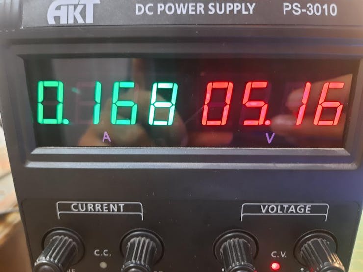
The power consumption is depended on the brightness. I am using 60 LED’s in series with each other and these are consuming a total of 170mA @5volts. A very small current of 2.2mA is drawn by each LED at 100 value brightness.
Connection circuit:
In the code you can change the Led pin to any digital pin and led count can be changed as per respective led strip used. Here I am using 4 stripes in series and each one has 15 led.
Every LED has a current limiting resistor, so you can connect the VCC of Stripe directly to +5volts. Arduino can be powered using a charger/ Adaptor of 5v-12volts.
#define LED_PIN 2 #define LED_COUNT 60
Working:

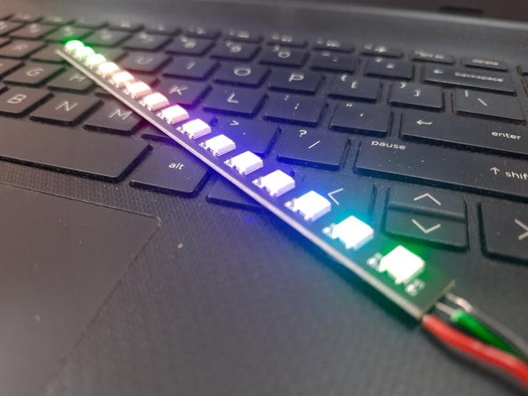
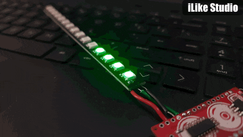
I Tried a lot of animations on these PCB, you can download the Neo pixel library to try different animations. After all I connected 4 PCB boards together to test the diffusion effect. Now it is ready to mount on the backside of my setup, so that it light when reflected from the walls looks like RGB, RGB = more FPS for gaming!
Design Drawing
BOM
 Clone
CloneAdd to Album
0
0
Share
Report
Project Members
Intellectual Property Statement & Reproduction Instructions
This is an open-source hardware project. All intellectual property rights belong to the creator. The project is shared on the platform for learning, communication, and research only; any commercial use is prohibited. If your intellectual property rights are infringed on EasyEDA, please notify us by submitting relevant materials in accordance with the Rules for Complaints and Appeals of IPR Infringement.
Users must independently verify the circuit design and suitability when replicating this project. All risks and consequences are borne by the user, and the platform assumes no liability.
Followers0|Likes0
Related projects
 Empty
Empty
Comment