

 Completed
Board AT90CAN128
PROBoard AT90CAN128
452
0
0
17
Mode:Schematic/Simulation
Reproduction cost: $12
License
:CC BY-NC 3.0
Reproduction is prohibited without the author's authorization
Creation time:2025-05-25 11:39:15Update time:2025-08-26 01:35:54
Description
Hello makers!
Here is a guy who likes to build various, small, electronic circuits, and through this application I would like to show you how I often use various components recovered from scrap electronics boards to create functional electronic circuits. I often do this, for various reasons, both economic and because if I have components at hand I am exempt from other things. 🙂
Here is a guy who likes to build various, small, electronic circuits, and through this application I would like to show you how I often use various components recovered from scrap electronics boards to create functional electronic circuits. I often do this, for various reasons, both economic and because if I have components at hand I am exempt from other things. 🙂
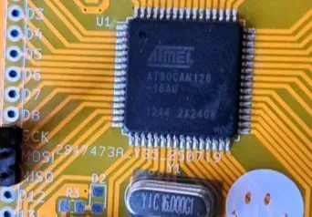
Recently I discovered an electronic board that contains an AT90CAN128 in a QFP package. Initially I thought it was an ATMega128 MCU (I also use an ATMega328, but I don't know all of them 😅), but then I did a search on the internet and discovered that it is a similar MCU that has some extra capabilities.
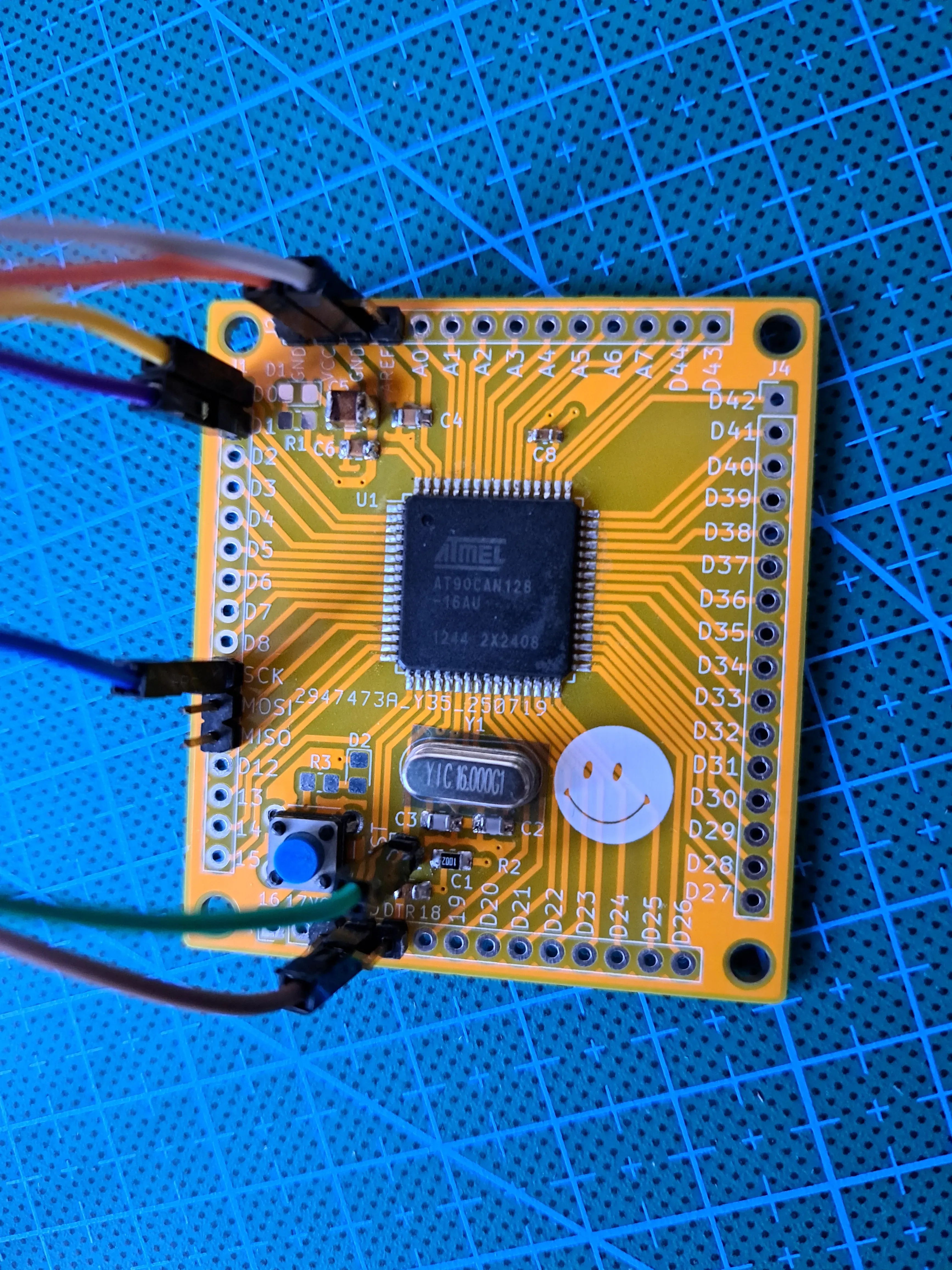
I plan to use this MCU to create a programmable board, through methods known to me, that is, by consulting the internet (forums and so on), and I even found information to program it using the well-known Arduino IDE (and from here we all know what a wide world has formed around Arduino 🤓), but I also have difficulties on this path. Given that the MCU I found is in an SMD package, I cannot use it in optimal conditions on a test wiring, perforated, so I need to design a good PCB. t will be a 2 layers PCB, it is relatively minimalist, in the center of attention being the AT90CAN128, and next to it I will place male pin headers to facilitate access to the GPIOs. This is the electronic circuit (quite complicated to understand 😆😅):
Maybe you think the dimensions are a bit generous, but I don't mind, it's one sample.
Let's not forget the bill of materials, except for the pin headers, of which I don't have many, the rest of the components are recovered from other electronic boards. Regarding the other components (resistors, capacitors) I will use both SMD and TH, I have them on hand (just what I said at the beginning). This board will be powered by 5V, so it's definitely handy, plus many electronic modules work at 5V.
With the help of the Arduino IDE and the available libraries, I will install the board and program the AT90CAN128 via a USB AVR programmer (from the MCU I need the signals: Reset, Mosi, Miso, Sck). What I can do next I have many options, if I have a board with many ports I can use it with environmental sensors, 16x2 display, common modules after all. I have enough ports to attach many LEDs, and for some time I have been thinking about an application with TTP223 touch buttons and RGB LEDs, to create a dynamic light panel or a small table, depending on resources (3D printing would also be needed and this part is a bit tricky) and time. But I also have a more feasible and equally brilliant alternative, 4x4x4 LED cube.In the end, I think that the outline of an application goes something like this:

So, to successfully build this board I would need:
1. Manufacture a professional PCB;
2. Assemble the components that I recovered from other boards;
3. Check the programming instructions with Arduino IDE and software libraries;
4. Take out the USB AVR programmer from the monkeys box 🙈.
So, after solving all the above, I still have to experiment with the programming tools and then we are ready to go.
Have a great day!
Update!!!
This is how it looks (partial assembly):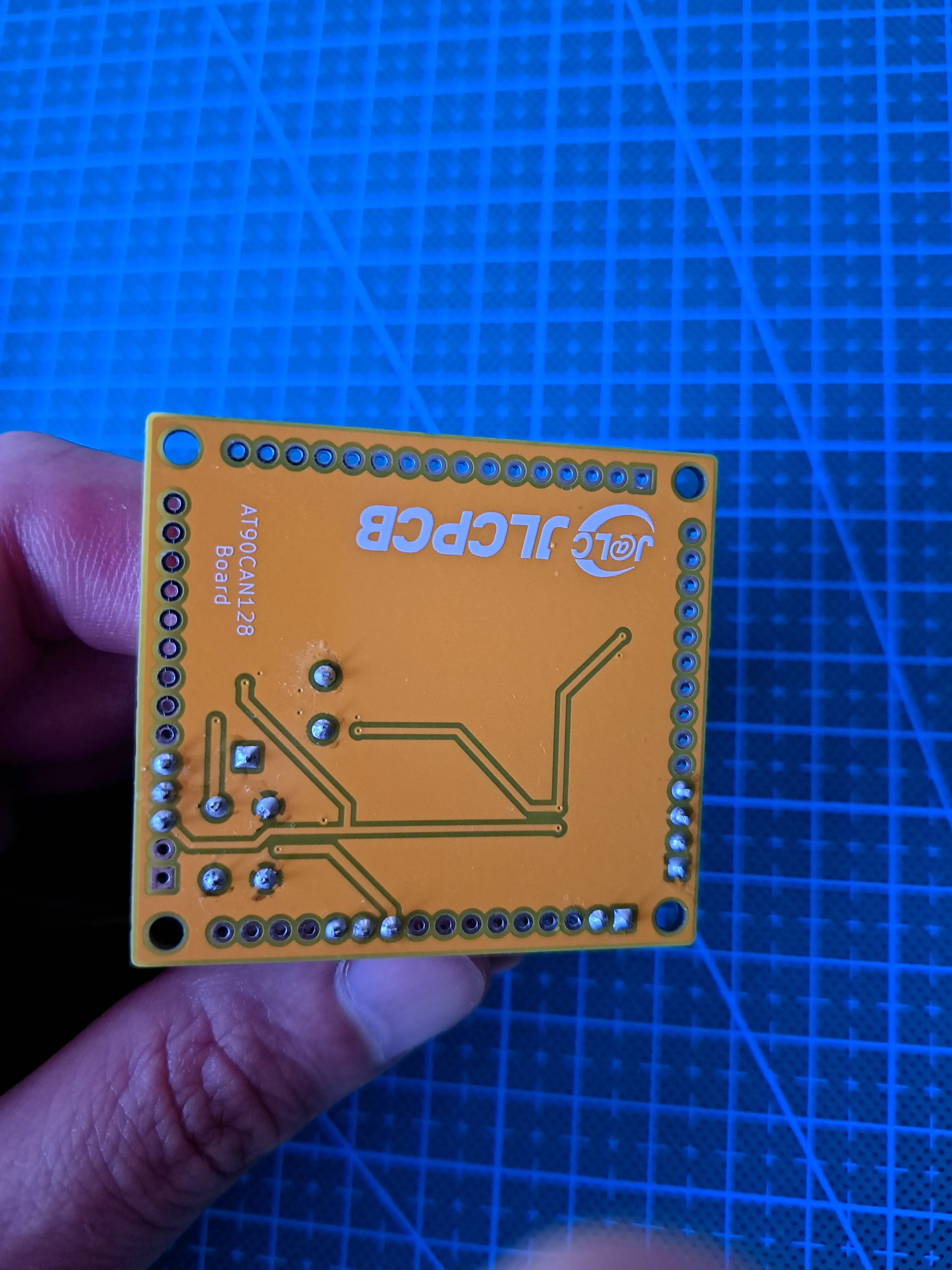
Design Drawing
BOM
 Clone
CloneAdd to Album
0
0
Share
Report
Project Members
Intellectual Property Statement & Reproduction Instructions
This is an open-source hardware project. All intellectual property rights belong to the creator. The project is shared on the platform for learning, communication, and research only; any commercial use is prohibited. If your intellectual property rights are infringed on EasyEDA, please notify us by submitting relevant materials in accordance with the Rules for Complaints and Appeals of IPR Infringement.
Users must independently verify the circuit design and suitability when replicating this project. All risks and consequences are borne by the user, and the platform assumes no liability.
Followers0|Likes0
Related projects
 Empty
Empty
Comment