The V1 version and the V2 version are not universal, please pay attention to distinguish them!
If you have any questions, please leave a message
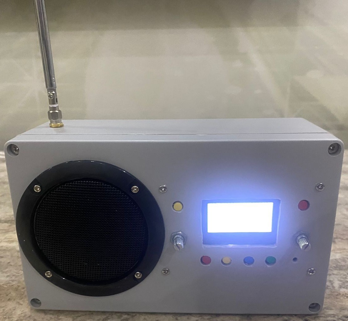
The SAF7751 radio board module and control board V1 version information is as follows:
receiving frequency band
FM, FL, MW, LW, SW
introduction
RF reception: NXP SAF7751 radio supports long wave, medium wave, short wave, and FM band reception.
Power supply: TYPE-C fast charging input, built-in charging power management, lithium battery can be installed and carried with you.
Audio: headphone amplifier;
More
The backlight brightness is adjustable and can be turned off, and the backlight time is adjustable.
The threshold and speed can be set for automatic station search, and stations can be saved manually.
Power-off memory settings and saved stations
Control parts:
For details, please see the attached file: Button Control Instructions.
Installation method:
Please refer to the attached installation instructions for details of the illustrated version.
1.Insert the M2*7 bolts into the bottom shell and fix it with the 20mm high copper column nut.
2.Install the ipex to sma female adapter cable, and install the cable between the control board and the system board. The cable spacing is 2.54mm;
3.When installing a polymer lithium battery, you can select a lithium battery of appropriate size and thickness according to the distance between the boards.
4.Put in the control board, pay attention to aligning the copper pillar holes, and install the key cap. The key cap specification is A101, and the inner diameter of the cap is 3.4mm.
5.Use a 5mm high M2 copper post with threads to fix the control board and the lower 20mm high M2 copper post.
6.Install the panel on the radio and fix the four corners with M2*7 bolts and the 5mm-high M2 copper pillars on the lower layer.
7.Install the knob bolts to fix the knob and the panel;
8.Install the aluminum alloy knob cap (13*13 plum blossom shape) and antenna, turn on the phone and plug in the headphones to listen.
Control board firmware source code open source address:
https://github.com/rayc345/WTCRC775X/tree/master
The attachment is available for download
The data in the M25P16 memory chip of the system board can be flashed with the software in the attachment. The flash device CH341A programmer is as shown below.

Radio Shell
The attachment of the 3D printed shell has been uploaded, and M2 copper posts and bolts are used to connect the shell
3D printed shell with dimensions of 106x68x35mm. The saf7751 chip generates a lot of heat, hence the panel features a lot of heat dissipation slots.
V3.1 control board waterproof case:
V3.1 version control panel:

Notes on the Release:
1. The text on the 5V LCD1602 is blurred when powered by a battery because the voltage is not raised. Use the 3.3V LCD1602 instead, and simultaneously update the schematic diagram and PCB. (20230329)
2. Address difficulties with mid-circuit packing and differential pair wiring. (20230427)
3. If a mistake is found in the system board schematic diagram, the PCB will be modified at the same time. (20230610)
********* ********* ***
4. The general control board MCU in the V2 version is replaced by stm32L051c8, and the display screen is replaced by 12864. (20230531)
5. The universal control board's V2 and V3.0 versions only support external speakers.
6. The V2 version lacks a shell file, which will be added later depending on the situation.
7.The V2 version control board 6638 radio board has been verified and is being continuously optimized.
8.Adjust the positions of the V2 control panel display, infrared and electrolytic capacitors. (20230620)
9.Update the TEF6686 radio board to V3, ensure that the upper and lower boards are the same size, and lead out DAC_L and DAC_R at the same time. (20230628)
10.Update the power amplifier control circuit of the V2 control board. (20230630)
11.The V2 version and 7751 radio board and the V3 version 6686 radio board have been successfully verified. All PCBs currently open source have been successfully verified. (20230705)
12.The general control panel is updated to version V3.0, the rotary encoder type and button position are modified, and a dual-speaker amplifier is adopted. (20230710)
13.The general control panel has been updated to version V3.1, and a headphone holder has been added, which can connect to external power amplifiers and speakers. (20230714)
14.Update the power amplifier control circuit of V3.0 and V3.1 control boards. (20230729)
15.Delete the V2 and V3.0 control panels, leaving the V1 version control panel, V3.1 version control panel and each radio panel. (20230802)
16.The V1 version control panel is only applicable to the V1 version of the radio board, and the V3.1 version of the control panel is only applicable to the V2 and V3 version of the radio board. (20230802)
17.There will be no further updates!


 Ongoing


 Clone
Clone Empty
Empty
Comment