

 Ongoing
"OneShot" LED headlight
PRO"OneShot" LED headlight
License
:GPL 3.0
Description
Copyright belongs to @核子-NUCL
link: https://oshwhub.com/qxqpcb/fu-ke-you-hu-OneShot-Nikode-deng
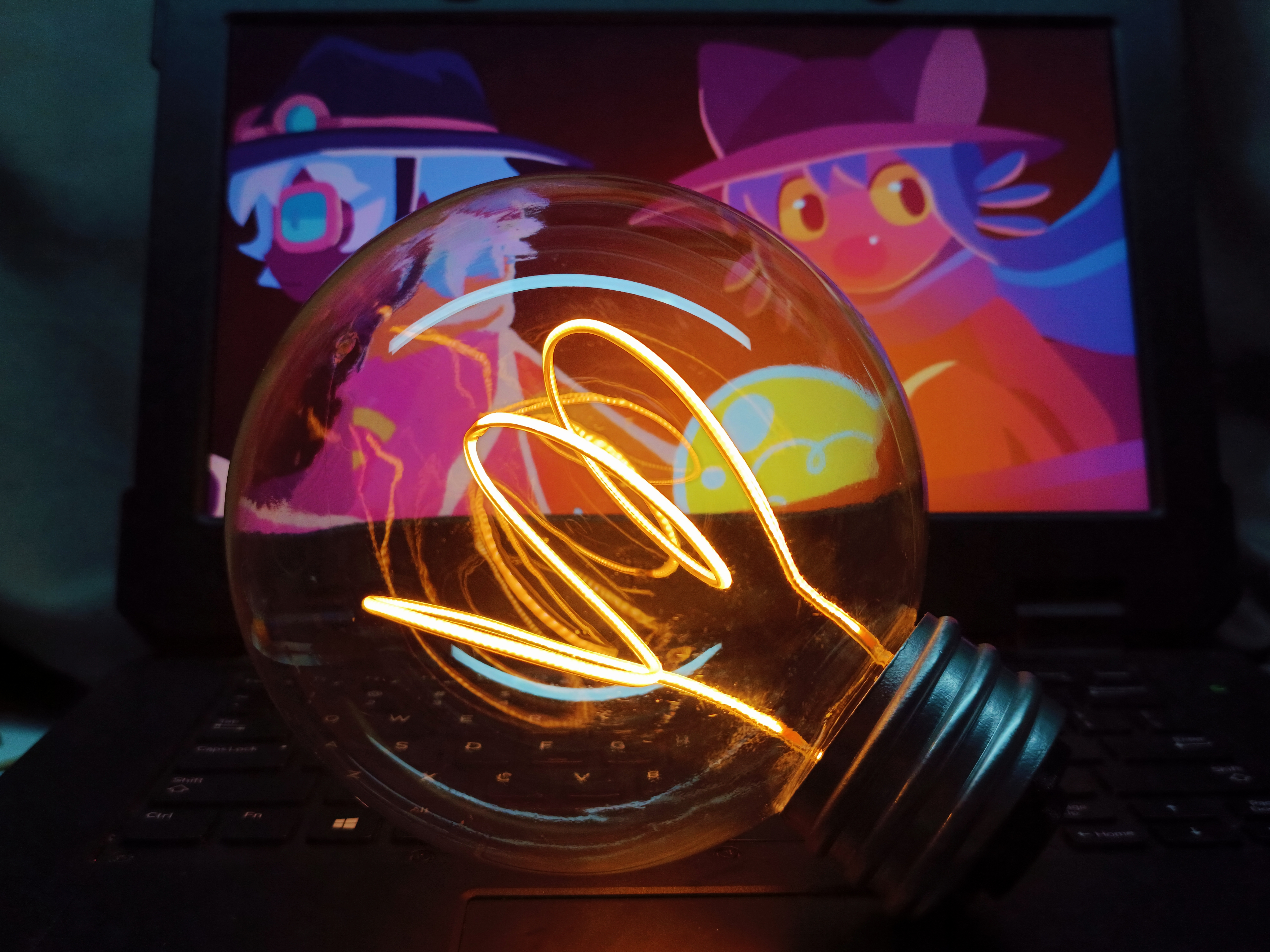
In February of this year, I played a game called OneShot, in which Niko, the main character, is holding a large light bulb, and I was fascinated by it. So I decided to utilize my spare time to create a light bulb similar to the one in the game. After months of searching and testing, I finally came up with a bulb that I want. I hope this big light bulb can bring joy and surprise to everyone.
Application Scenario: home lighting, crafts.
Functions: touch/proximity (light bulb) sensing, touch (light tail) infinitely dimmable, Type-C charging.
The work has been published in the sixth issue of Radio magazine in 2023. if you are interested, you can redeem the magazine with your points in the open source platform.
As of July 7, 2023, I have updated the second generation of the LED big light bulb motherboard, the second generation of the motherboard is more suitable for DIY production.
The finished product has been sold in Xianyu secondary market and Bilibili Workshop. You can search for LED Big Bulb to find the item.
Design solution:
This work has the advantages of practicality, personalization, portability, energy saving and environmental protection. The production principle is simple and easy to understand, suitable for personal DIY.
This work is powered by 3.7V polymer lithium-ion battery and charged by TP4056 lithium-ion charge management chip.
This work has two functions, proximity sensing and touch sensing, through the toggle switch can choose two kinds of light sensor mode:
*A-Microwave radar touch/proximity sensing: the light bulb can be lit by touching or approaching the light bulb. (Bulb brightness is the maximum brightness)
*B- Infinitely dimmable touch sensing: By touching the specified position on the end of the lamp, the bulb can be lit, and touching again can adjust the brightness of the bulb.
Materials Selection:
1.Transparent shell: the light bulb shell is a customized product, you need to find a manufacturer to customize.
2. Filament: filament using flexible LED filament, the filament is also the beginning of production in recent years, using a special process molding. Lamp beads are arranged more densely, compared with ordinary LED light strip, flexible LED filament luminous uniformity, filament diameter is small. Suitable for the production of the work filament.
The filament is made of two 300mm long flexible LED filaments, stainless steel wire, heat-shrink tubing and enameled wire. Processing difficulty is slightly larger, the two filaments are connected in parallel; this side is not recommended in series, because of this, drive the motherboard requires a boost module.
3. Lamp tail shell: lamp tail shell by light curing printing molding, need to use black acrylic paint, electroplating spray paint, varnish protection paint, dyeing and protection.
4. Filament fixing parts: The model has certain requirements on the flexibility and rigidity of the consumables. Use FDM print molding as much as possible. You can use PLA, ABS and other materials to print.
5. Sensing module: The sensing module adopts HLK-LD102 10GHz radar sensing module of HELINKA, which has a small sensing distance and can customize the sensing parameters as well as the working mode through the upper computer.
6. induction dimming module: the chip adopts the RH6618A chip produced by Ronghe, the chip also comes with a touch sensor.
Design principle:
1. induction dimming: using a single-channel touch-type IC-RH6618, the chip compared to the SGL8022W, RH6618 PWM frequency is higher, the dimming is more silky smooth, and effectively improve the strobe problem.

RH6618A realizes touch dimming by touching the TCH pin by human body. When the chip is working, the POUT pin outputs a PWM signal, which is connected to the gate of NMOS tube to drive the LED soft filament with higher current.By controlling the high and low levels of the mode configuration pins (MOD1, MOD2) to change the infinitely dimmable mode of operation, MOD1, MOD2 is high by default. MOD1 and MOD2 are high level by default. When configuring high level, connect directly to the positive pole of the power supply, or directly suspend the pin, and configure low level to ground the mode allocation pin. TCH is a touch-sensitive pin, touching the copper foil can realize the sense, can be attached to the copper foil on the non-metallic sheet to realize the touch-sensitive.
BAT and B+ in the figure are both power positive, in order to switch mode (touch infinitely dimmable and radar sensing), and separate them, in the complete circuit, B+ is the switch third gear positive output.
Below is the output mode configuration table from the RH6618 datasheet:

NO.2 as an example, we will be mode mating pin MOD1 ground MOD2 suspended or connected to the positive terminal of the power supply (VDD) can be configured for mode without brightness memory dimming dimming induction dimming function.
2. lithium battery charge management: TP4056 lithium battery charge management chip. The chip is low cost, good performance, widely used.
Access to 5V power supply, when the LED1 light, indicating that the battery is charging. When LED2 lights up, that is, the battery is fully charged. Among them, BAT connected to the positive pole of the lithium battery.

We can change the value of the resistor (R8) next to the PROG pin to limit the power management chip charging current: RPROG = 1200/IBAT (error ± 10%)
For example:RPROG=1200Ω IBAT=1000mA; RPROG=2400Ω IBAT=500mA; RPROG=12000Ω IBAT=100mA.
Microwave radar module:
The module adopts HLK-LD102 10G microwave radar module. Based on the Doppler radar principle, it can realize the detection of motion and micro-motion. The product can support modification of sensing parameters.
After downloading the firmware of this product from HLK website and connecting the radar module to the computer via USB to TTL module, the sensing parameters of the radar module can be modified.
Here we trigger the radar module by touching or approaching the light globe by hand. I modified the control mode: 3 (the light gradually brightens after the condition triggers, and fades out after triggering again.) Blocking time: 2000 (Cannot be triggered again within 2000ms after triggering. Prevents repeated triggering for a short period of time.) Threshold: 500 (The smaller the threshold value, the more sensitive the trigger.) Distance: 255 (The larger the value, the larger the sensing range, the maximum value is 255.)

Production process:
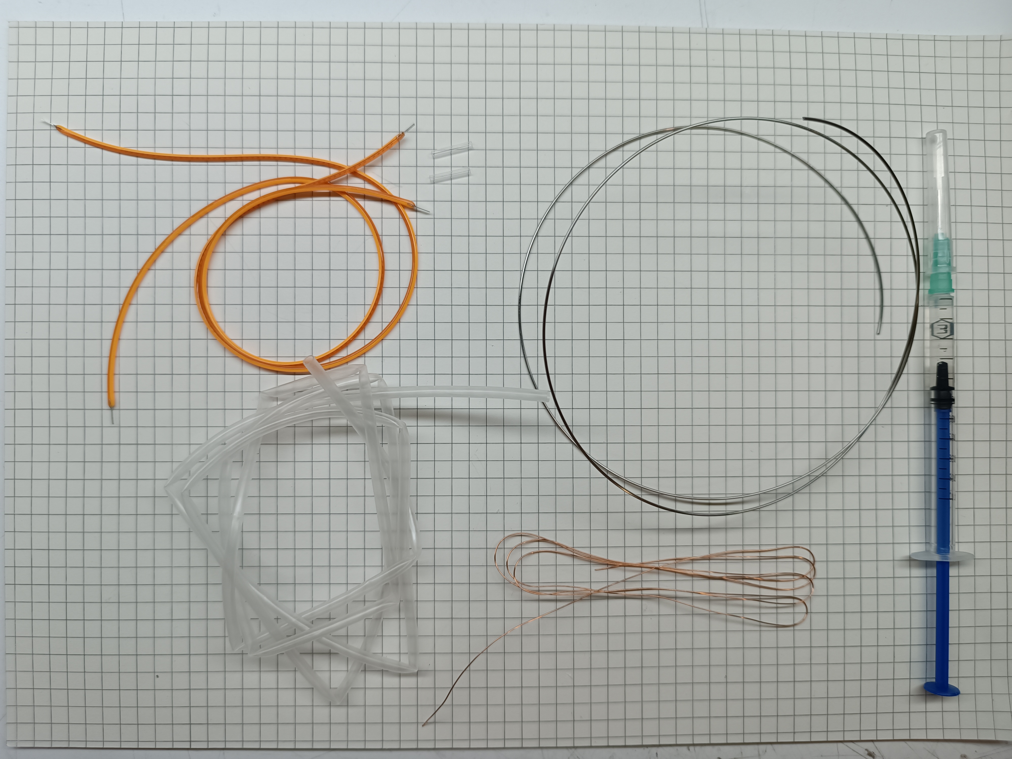
1. Need to prepare: LED big light bulb motherboard, copper foil tape, USB to TTL module, serial port adapter small board, ZH1.5mm-2pin row wire, ZH1.5mm-5pin row wire, Dupont female wire, wound semi-finished filament, radar module, 103030 polymer lithium batteries, light tail housing, filament fixing parts, custom big light bulb shell.


2. Make Filament: the required materials are flexible LED filament, heat shrink tubing, stainless steel wire, enameled wire, dimethyl silicone oil. The right figure for the LED filament and enameled wire welding, filament connected in parallel. The pins can be positive or negative, and are connected the same way in the end anyway.
Dimethicone is used for lubrication when sleeving heat shrink tubing. As for what to do with the sleeve, you have to figure it out yourself. Heat shrink tubing set of filament, heat shrink at both ends on the line, do not need to be heated as a whole, because this may lead to later filament damage chances.
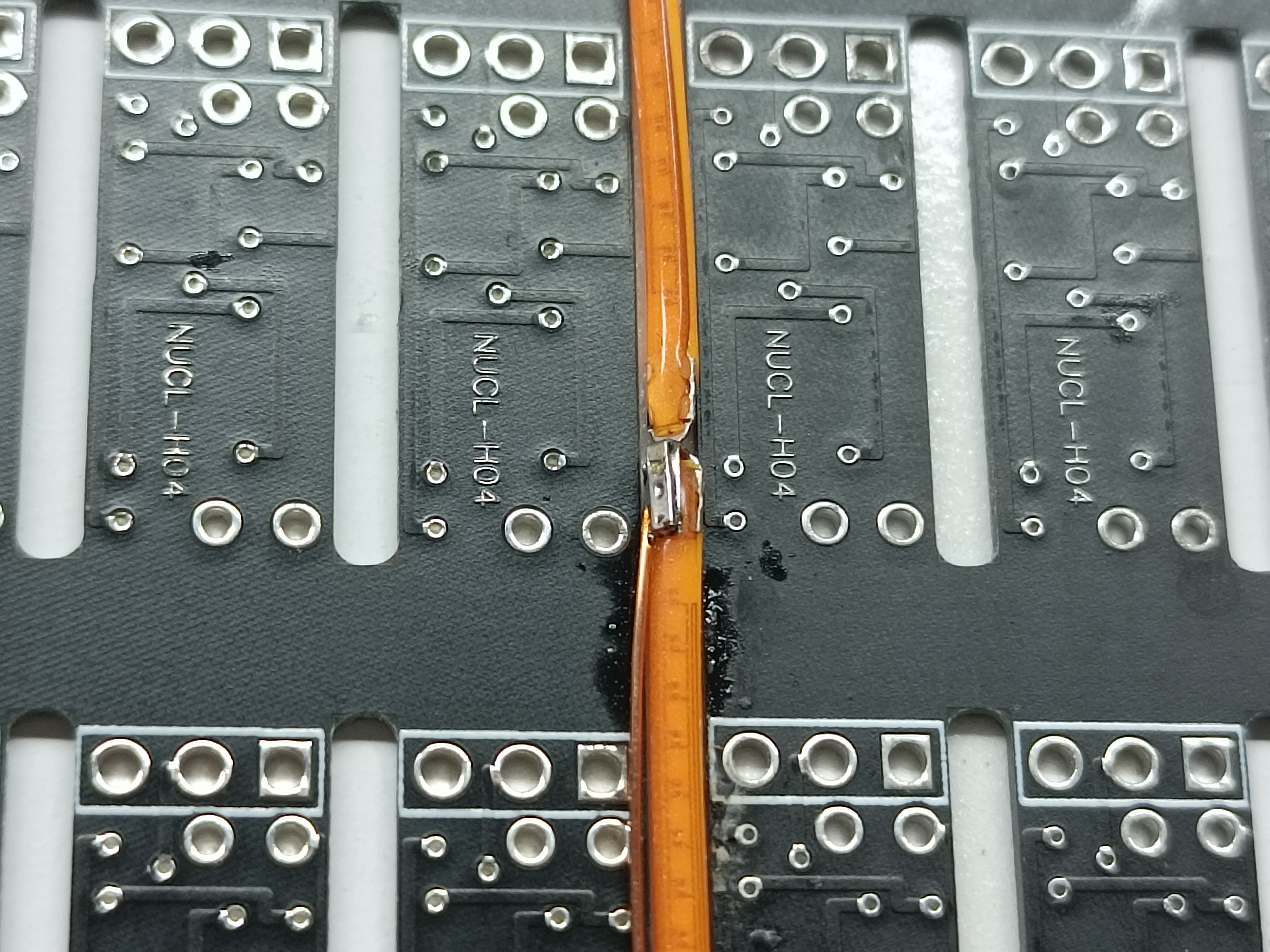
3. Radar module and line welding: as shown in the figure, the ZH1.5mm-5pin line pin welding to the radar module, the radar module is too long, you need to cut short half of the part, without affecting the welding of the module on both sides of the PCB board minus.
Radar module on the silkscreen definition: V for VCC, G for GND, O for OUT, RB1 for RX, RB0 for TX.
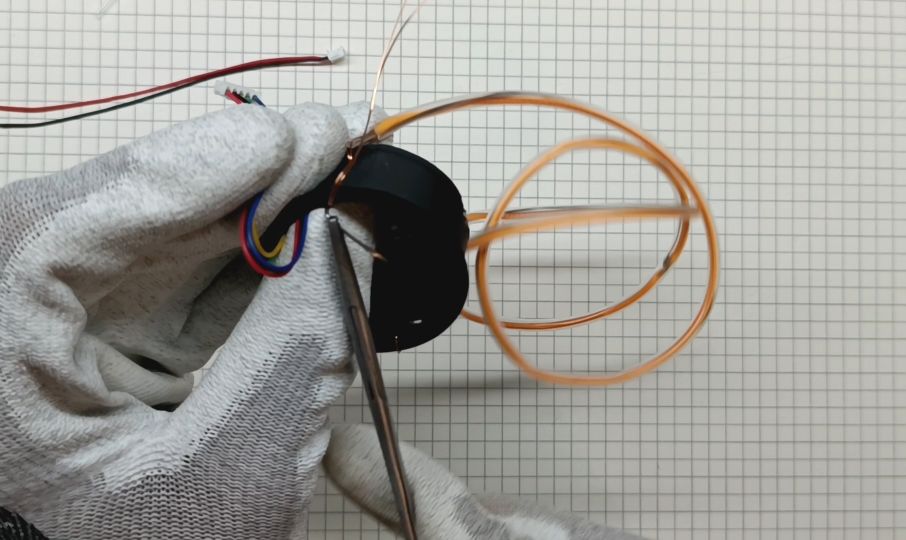
4. Assembly: Put the radar module on the filament fixing piece and use the hot melt glue to fix it, wait for the hot melt glue to solidify. Pass the semi-finished filament through the filament fixing piece. Then use pliers to bend the steel wire of the semi-finished filament to increase the contact area of the hot melt adhesive. Then apply the hot melt adhesive to the wire and the filament holder. Wait for the hot melt adhesive to solidify, and then use the soldering iron to solder the enameled wire in the filament and the ZH1.5mm-2pin wire, pay attention to the soldering should be 3V power supply to test the positive and negative poles of the filament.


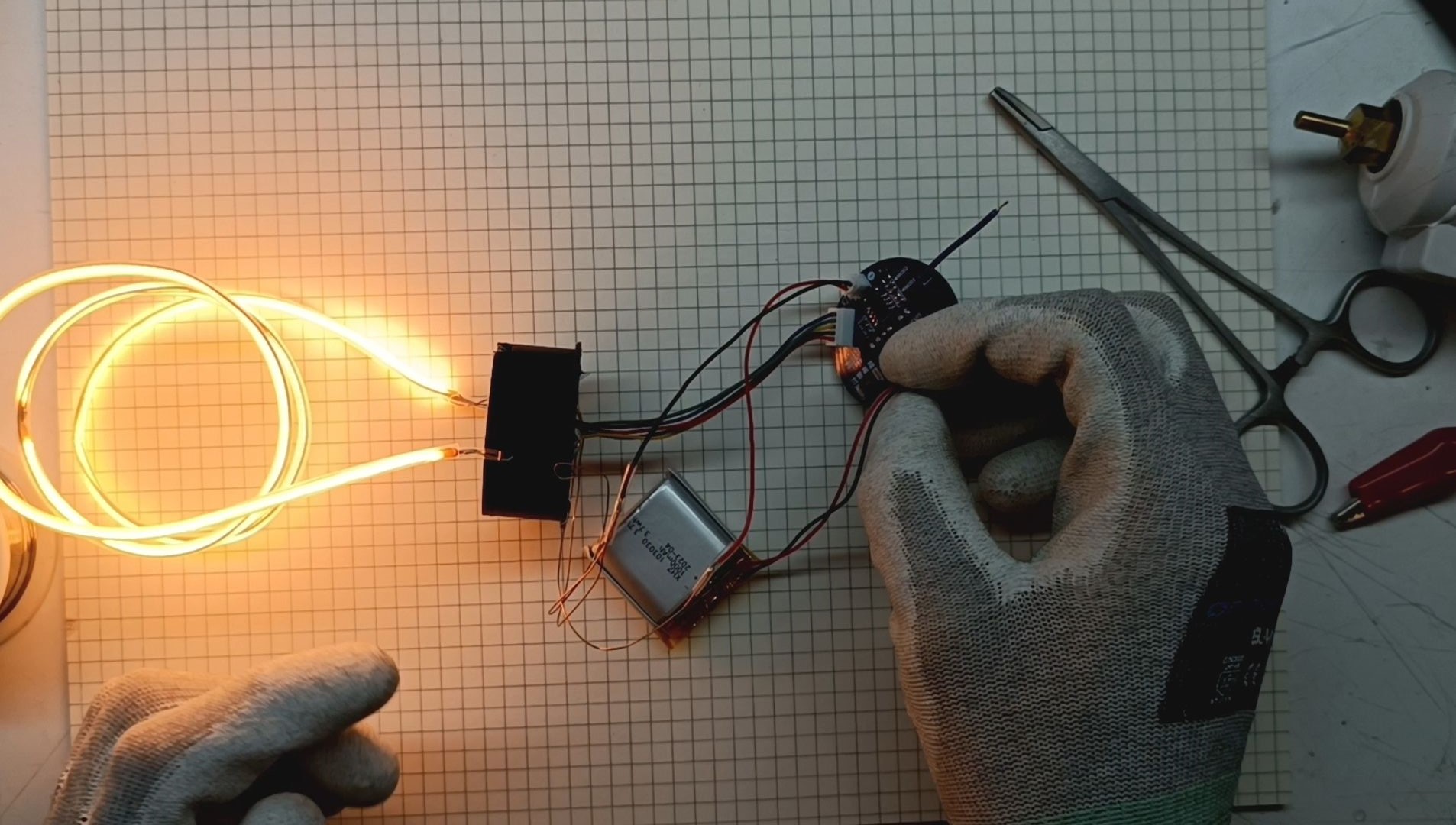
5. Connect the accessories to the motherboard and test
6. After testing that there are no missing functions and hardware, stuff the filament into the bulb and fine-tune the filament shape with your fingers. Caution! This process will be difficult and easy to damage the filament!
7. Put hot melt glue on the back of the motherboard, and fix the motherboard and the shell together while the hot melt glue is not solidified. Stick copper foil on the inner wall of the lamp housing, and then solder the TCH pin wires in the motherboard to the copper foil.
8. Connect the accessories, screw the shell to avoid wires on the internal threads, it is recommended to use tape to tie all the wires together, before screwing, you also need to rotate in the opposite direction for a week, so that you can avoid wires screwed more than one circle resulting in circuit breakage.

Product Demonstration:
Design Considerations:
When designing the circuit, we should place all capacitors near the corresponding ICs for better performance. For induction dimming ICs, we should avoid laying copper near them as much as possible, especially the TCH pins. In addition, we need to keep the distance between the surrounding alignment and the TCH line. Avoid unfavorable interference to the induction dimmer IC.
This work is slightly difficult to DIY, the filament is easy to break during installation, causing irreversible damage.
Design Drawing
BOM
 Clone
CloneProject Members
 Empty
Empty
Comment