 Completed
[Whole network first] Lightning 4 Laptop Graphics Card Dock
PRO [Whole network first] Lightning 4 Laptop Graphics Card Dock
License
:CC BY-NC-SA 4.0
Description
Project Brief Introduction
This project is expected to open source a Thunderbolt 4 graphics card box based on the JHL7440 main controller, and users can connect high-performance desktop graphics cards to laptops through the Thunderbolt interface to improve the graphics processing performance of notebooks. The graphics card box is designed with PD3.1 charging circuit, which can also charge the laptop while using the graphics card, and the battery pack and battery management system are also installed in the graphics card box, when the power supply to the graphics card box is disconnected, the battery pack will continue to supply power to the graphics card box and the user's notebook, avoiding the problem of game jamming and data loss when the power supply to the graphics card box is disconnected.
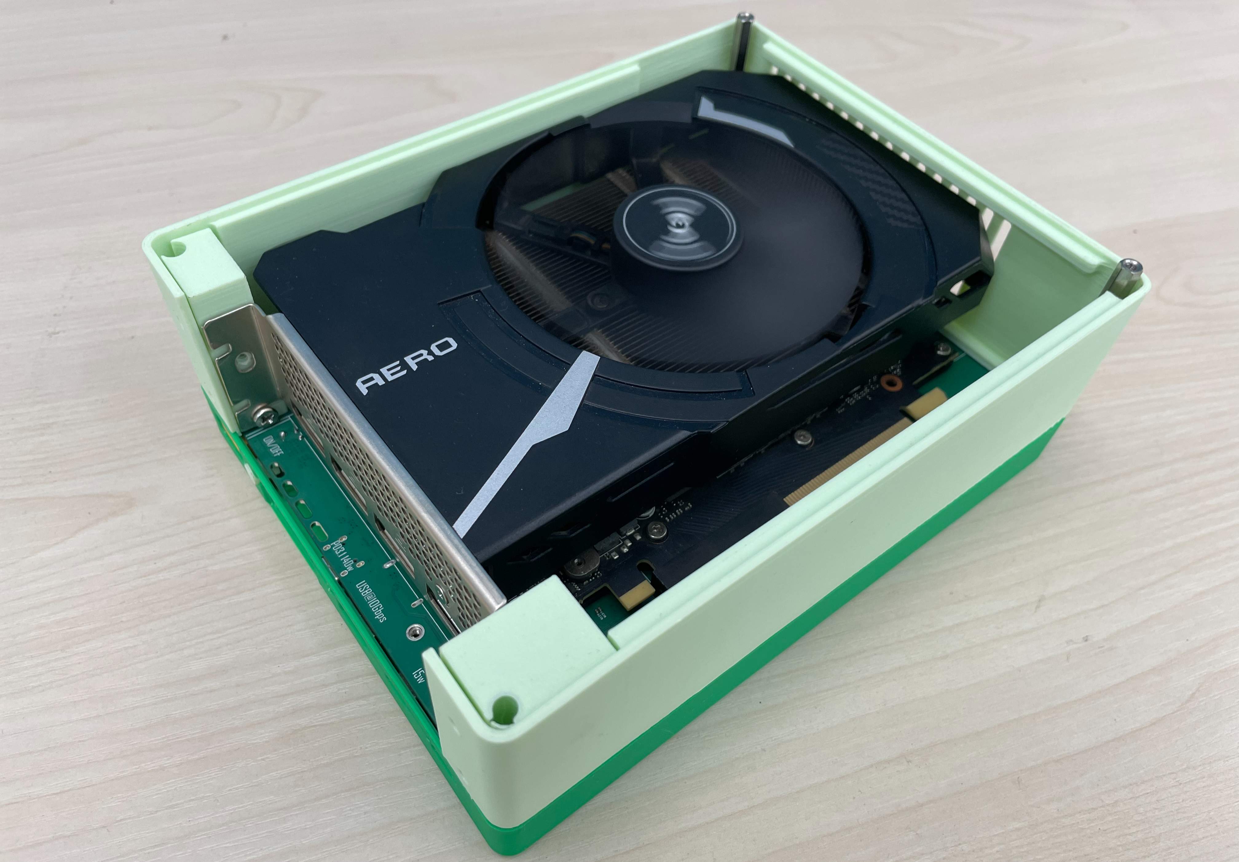
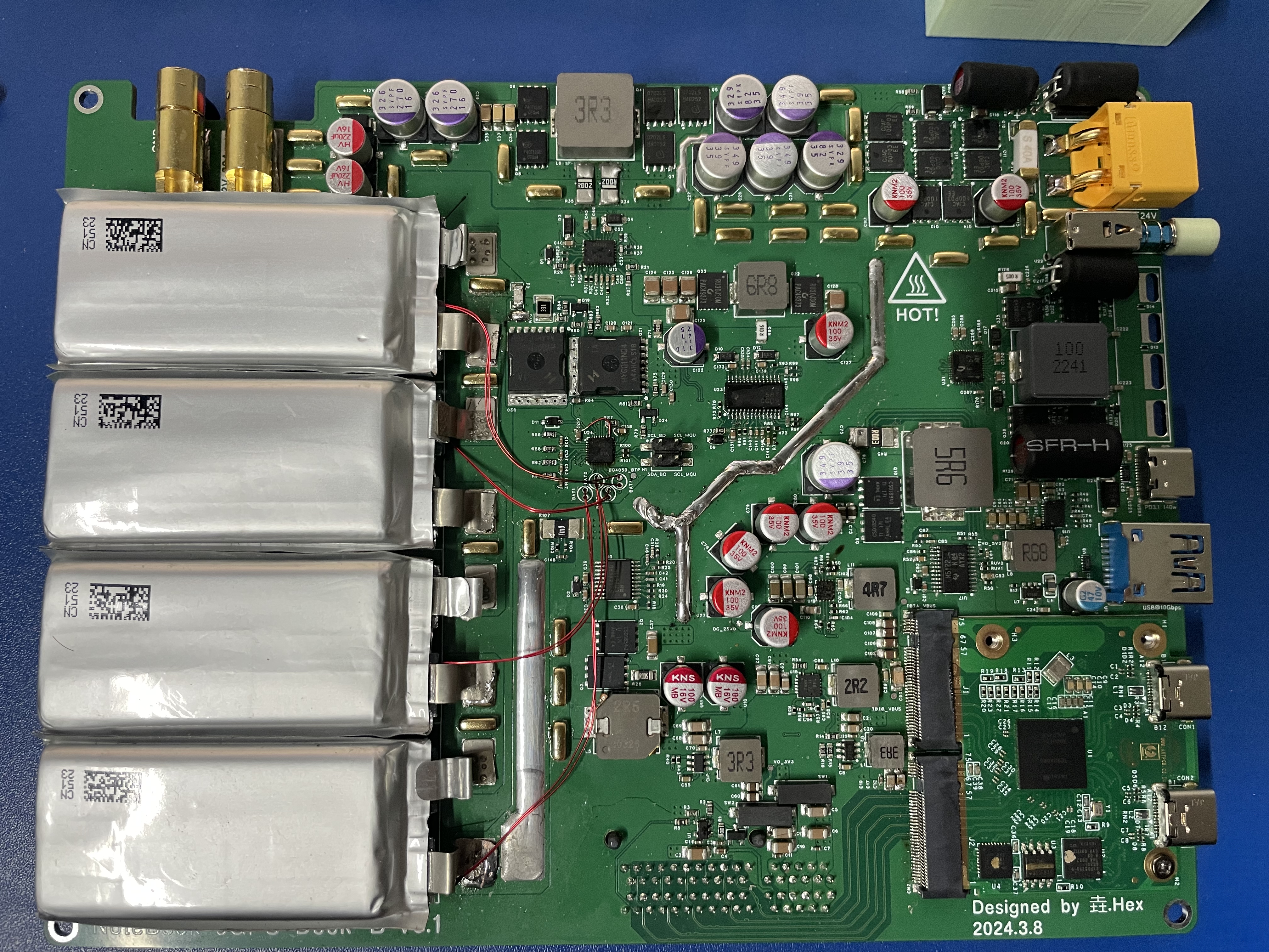
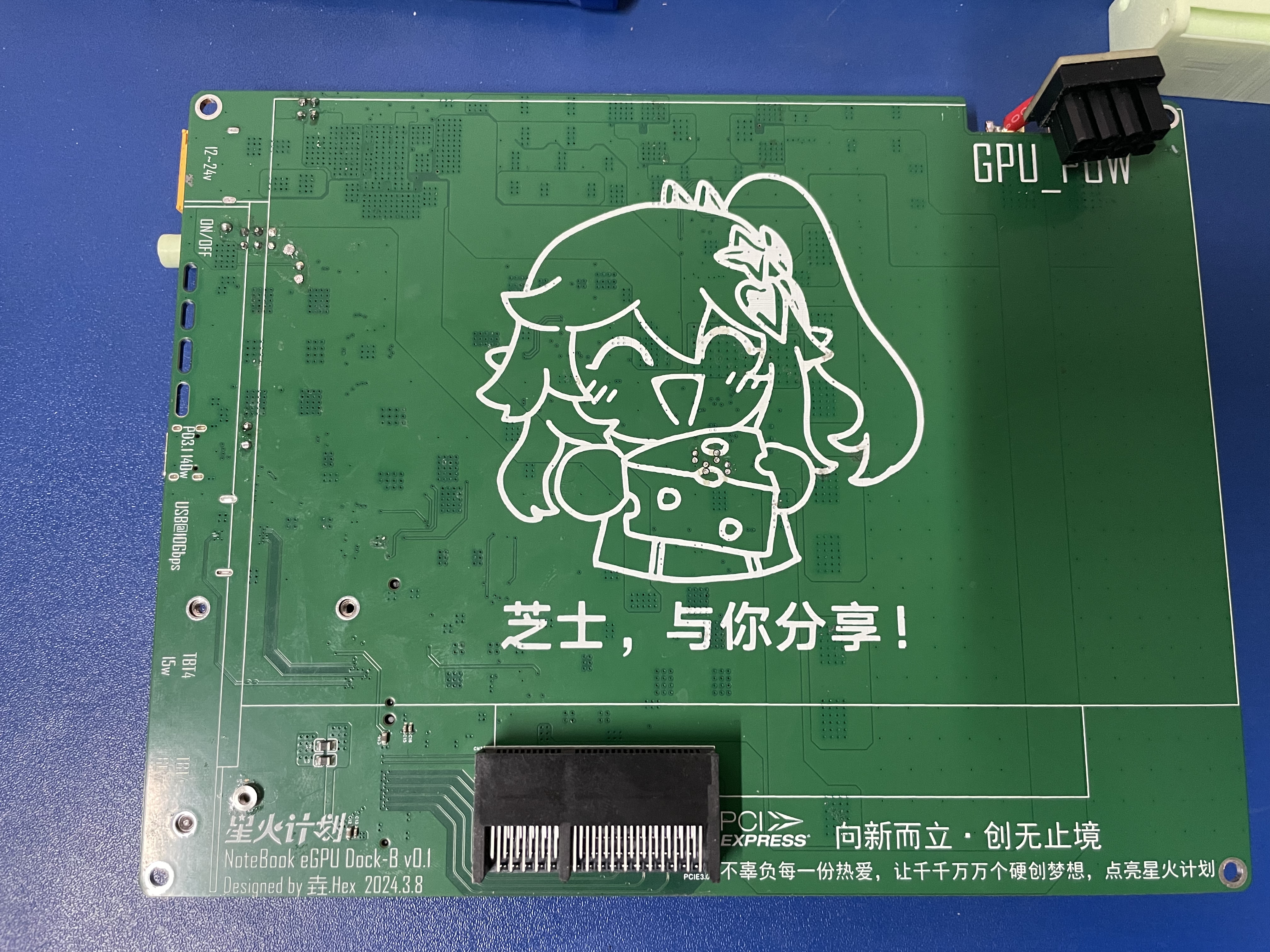
The finished picture and rendering of the graphics card box are shown in the figure:


Open-source Protocol
This project is licensed under the "CC-BY-NC-SA 4.0" Creative Commons license, please do not use it for commercial use, please indicate the source when reprinting.
Project Properties
This project is the first public and is my original project. The project has not won an award in another competition.
Project Updates
2024.4.4 The open source project Thunderbolt Notebook Graphics Dock was released. The main circuit version is: NoteBook eGPU Dock-B v0.2.
Project Progress
As of March 25, 2024, all indicators of the project have been completed and verified.
In addition to the project requirements, UPS circuits, PD3.1 charging circuits, USB10Gbps interfaces, buck-boost power supplies, etc., are additionally added to make the graphics card box additionally supportive.
- UPS function
- PD3.1 reverse charging function
- Wide voltage power supply
As of April 2, 2024, the verification of all the above functions has been completed.
Project parameters
Maximum graphics card power: 240W
Lightning transmission data bandwidth: 32Gbps
Maximum reverse power supply power of PD port:PD3.1@140W
Maximum reverse power supply power of lightning port:PD3.0@60W
Size: 190x148x68mm (LxWxH)
Project Introduction
1. Hardware introduction
1.1 General Introduction
The hardware circuit is divided into two PCBs, one is the graphics card box motherboard, which is responsible for power supply, PCI-E high-speed cable, and battery management. Another PCB negative battery parameter display, power-off alarm.
The motherboard power tree is as follows:

The system power supply can be divided into two working states, the first working state is powered by an external power adapter, from the left 12~24Vin is the external power adapter input, after entering the system, it is divided into two ways.One way to the Charger, through the BQ40z50 fuel gauge to charge the battery, the other to the PowerPath circuit, the PowerPath circuit will judge whether the main power supply is normal, if the main power discharge mos is normal, the standby power discharge mos is off. The mains power supply supplies power to the backing circuitry. The PowerSwitch is a power switch circuit, using Pmos as a high-side switch, when the user closes the mechanical switch, the Pmos will be turned on, and the power supply will be powered on.
The second working state is when the battery supplies power to the system, from the left 4S Li-ion battery enters the PowerPath circuit through the BQ40z50 fuel gauge, because the external power supply has been disconnected, PowerPath discharges the battery mos on, and selects the battery to supply power to the post-stage system.
PowerPath chooses to use battery power when the adapter voltage drops below 10.8V, and switches to adapter power when the adapter voltage rises back to 11.8V.
ThunderBolt Module2 High-Speed Cable Trace Diagram:

Motherboard PCB 3D as shown in the figure:


The hardware block diagram of the MCU board is as follows:

The MCU board is responsible for accessing the battery parameter data, power-off alarm, and temperature detection in the BQ40z50 fuel gauge. MCU selection STM32F103C8T6.
The MCU board circuit 3D is shown in the figure:

1.2 Introduction to the power supply (LM34936) of the graphics card
Since the project needs to support a wide voltage (11-24V) power supply, the graphics card works at 12V, so the input has to go through a DC-DC power converter to power the graphics card. And because the power consumption of the RTX3060TI graphics card can reach 240W at full load and the dynamic range is large, it is necessary to use a DC-DC power supply with high efficiency and good dynamic response.
This project uses TI's LM34936 solution, LM34936 a DC-DC power controller with a buck-boost topology, supporting a wide voltage input of 4.2-30V, and using current-mode in both buck and boost modes with excellent dynamic response performance. Using Texas Instruments WEBENCH power design software to generate circuit diagrams and simulate, the power efficiency can reach 97.2%, and the dynamic response simulation is as follows:

1.3 Introduction to PowerPath modules
Since both power supplies can supply power to the graphics card box, and when the main power supply is disconnected, the secondary power supply needs to replace the main power supply to power the device immediately, and there can be no switching delay. So choose LTC4416 chip. LTC4416 is a dual-channel power path management chip that uses a hardware comparator to control the power switching circuit to achieve the fastest power switching. It is measured that 0s switching can be achieved under 20V 20A load, as shown in the figure:

In the figure, channel 1 is the output voltage of the power adapter, and channel 2 is the output voltage of the PowerPath circuit, at about 240mS, the external adapter is powered off (1 channel), and the PowerPath circuit switches to the secondary power supply at the moment of power failure, and the voltage drops to the secondary power supply voltage (2 channels).
The resistors of the three hysteresis comparators need to be configured before use, and the formula is available in the data sheet and in the engineering circuit diagram.
1.5 BQ40z50 fuel gauge
The device requires 400W of power supply when running at full load, and the load is more dynamic, which puts a lot of pressure on the battery. Due to the internal impedance and load dynamics of the battery, there is a great test for the battery power statistics. This project uses a BQ40z50 fuel gauge with impedance tracking algorithm, this fuel gauge can measure the impedance of the battery pack, no matter how the load changes, the fuel gauge can find the open circuit voltage of the battery pack, and through the early chemical parameter matching, you can get the power corresponding to the current open circuit voltage.
2. Hardware index test
2.1 Ripple and dynamic response of the graphics card's power supply
Turn the oscilloscope to AC coupling, the bandwidth is limited to 20M, the probe uses x1 gear, uses the ground spring to ground, and the measured ripple of the graphics card power supply when it is no-load is shown in the figure:

The ripple size is 24mV.
The ripple measured at full load of the power supply is shown in the figure:

The full-load ripple size is 35mV.
Test Scenario:

The dynamic electronic load is connected to the power supply, and a 100Hz 1100mV square wave signal is generated by using a signal generator to control the electronic load to generate a step current signal. The dynamic response of the power supply is obtained as shown in the figure:

In the figure, channel C2 is the output current of the power supply, and channel C1 is the voltage of the power supply. AC coupling is enabled on the C1 channel, and the bandwidth is limited to 20Mbit/s. When the current rises from 0A to 11A, the overshoot of the system is about 72mV, and from 11A to 0A, the overshoot of the system is 61mV, and the dynamic response is good.
Dynamic Response Test Scenario:
2.2 Thunderbolt 4 Bandwidth Test:
 Test Environment: Laptop: Legion Y9000X 2023 (IAH7)
Graphics: MSI AERO RTX3060TI LHR
Cable: JEYI Passive Thunderbolt 4 data cable 25cm
Test software: AIDA64 Extrame
2.3 System Heating Test:
Use a thermal imager to check the PCB temperature when the battery is not fully charged, no devices are connected to the system, and no thermal pan is installed:

PCB temperature when the adapter is used for power supply, the battery is not fully charged, the system is fully loaded, and the heat sink is not installed:

Test equipment: Hikvision K20
Notes on forking:
1. Parts that need to be purchased
- THUNDERBOLT MODULE2 MODULE, AS SHOWN IN THE IMAGE:

- High voltage lithium battery, model: 1102760, capacity 1.95AH, as shown in the figure:

- 14AWG silicone wire, used to power the graphics card, connect the graphics card and the graphics card box.
- SMD solder copper block, 6*2*2mm, is used to assist heat dissipation and increase the overcurrent capacity of PCB leads
- 5557 splint type 8P graphics card solder plug for graphics card power supply, as shown in the figure:

- 6.5mm banana head connector, used to connect the graphics card and graphics card box motherboard, male and female need 2 each, as shown in the figure:

- 7*5*0.3mm cold solder tabs, used to connect the battery with the graphics card box motherboard, 8 pcs are needed, as shown in the figure:

- 0.96-inch LCD screen, ST7735S main controller, used for MCU board to display system parameter information, as shown in the figure:

- Screws: M2*4, M2*16, M3*8
- Studs: 4 M3*45+10
- Power adapter: 12~24V is OK, according to the graphics card used, I use the RTX3060Ti graphics card, the graphics card box is charged to the laptop at the same time when it is working, and the 245w*2 gallium nitride power supply of HOTA company is used, and the measured can work stably. If the power supply is 12V, the full-load voltage drop of the power supply should not be too large, if the input voltage is less than 10.8V, the system will think that the external power supply is abnormal and switch the battery power supply.
- 8mm heat shrink tubing for capacitor aluminum shell insulation.
2. PCB Fabrication
2.1 Proofing
This project requires 3 PCBs from the proofing project: GPU_Dock_MotherBoard, MCU_Board and 8p connectors.
GPU_Dock_MotherBoard When placing an order for PCB, choose JLC04161H-3313 laminate structure, which requires impedance control, ± 20%, 1.6mm thickness. The other PCBs are also 1.6mm thick, so there is no need for impedance control.
2.2 Soldering
2.2.1 Talk about some notes in the front
Finally solder the battery! Finally solder the battery! Finally solder the battery!
The layout of PCB components is relatively dense, if you do not choose SMT, it is recommended to solder the chip first, and then solder the resistor capacitor, otherwise the chip will not go down the soldering iron if it is connected to the tin.
After all the components are soldered, do not plug in the Thunderbolt module2 module, power on the test first, and then plug in the module test after the power supply is normal.
The computer can identify the graphics card and perform a stress test, and then solder the battery if there is no problem, and be careful not to short circuit.
2.2.2 PCB after soldering 

2.2.3 Welding precautions
Pay attention to the insulation on the front of the PCB: the NTC resistor model of BAT1~BAT4 is MF52B103F3450, or use the B3450 10K resistor instead. Since this NTC resistor uses a through-hole pad, the backplane of the graphics card is in direct contact with the front of the PCB, and the pins need to be smoothed on the front of the PCB, and then insulating paper is pasted to prevent the backplane of the graphics card from short-circuiting the resistor, the same is true for C217 and U22.
Capacitor insulation: Capacitors with C113, C114, C217, and C221 capacitors need to be covered with heat shrinkable tubes and then welded to prevent short circuits in the aluminum shell of the capacitor.
Pay attention to the battery welding sequence: first weld the battery with the symbol B4, then weld B3, and so on.
NTC Resistor Position: A total of 6 NTC resistors are used in this project, 4 NTC resistors detect the battery temperature, and 2 NTC resistors detect the power supply and power path management temperature of the graphics card. The 4 NTC resistors that detect the temperature of the battery need to be glued to the battery and 704 silicone rubber can be used. In addition, the NTC resistor of the graphics card power supply needs to be glued to the inductor with bit number L6, and the NTC resistor of the power path management needs to be glued to the vicinity of Q14 and Q13.
2.3 Program Burning
After the PCB soldering is completed, power on, check whether each power supply is working normally, and the power supply voltage is all normal, and the module and graphics card can be inserted. After plugging in, use Thunderbolt 4 to connect the graphics card box to the computer, the computer should be able to recognize that there is a new GPU, if it does, it means that the main part is soldered without problems.
2.3.1 Fuel Gauge Configuration:
EV2400 is required to configure the fuel gauge, which can be purchased from a treasure for about 120 yuan. The EV2400 is shown in the following figure:

Then you also need to download a Battery Management Studio from the official website of Texas Instruments, or use the one uploaded from the network disk. Connect the SMBD and SMBC interfaces of the debugger to the SDA_BQ and SCL_BQ pins of the graphics card board motherboard, respectively. The PCB does not have a reserved GND interface, and you can use a lightning cable to connect the computer and the graphics card board to make the graphics box motherboard and the debugger co-ground. Once connected, open Battery Management Studio. Normally, this interface should pop up:

If this interface pops up, Auto Detected Device: None proves that the fuel gauge and the computer have not communicated successfully, as shown in the figure:

If the software can read the version of the EV2400, the EV2400 is connected to the computer. It is necessary to check if there is a problem with the soldering of the circuit.

If you cannot detect the version number of the EV2400, you need to check whether the EV2400 is properly connected to the system and check whether the Windows system will give a prompt when the EV2400 is plugged in. If the system prompts and the version is still not detected in the host computer software, there may be a problem with the system environment, you can try running Battery Management Studio on another computer or virtual machine.

The fuel gauge in the PCB is BQ40Z50-R1, and the R1 firmware is burned by default. The network disk link is configured according to the R2 firmware.You need to upgrade the firmware.For details, refer to the fuel gauge configuration video.
Other
After testing, this project can run stably on redmebook 14, Thinkbook 14+, Legion Y9000x. Some Lenovo thin and light laptops will have the situation that Thunderbolt 4 is incompatible, which is mainly manifested in the fact that Thunderbolt 4 will be disconnected within a few seconds after connecting to the graphics card box.
Annex
Link: https://pan.baidu.com/s/1yPTTYX021ZoxA8l5VQojqw?pwd=0udn
pwd: 0udn
Designed by Leo_Lin (from OSHWHub)
Link:https://oshwhub.com/leo_lin/jhl7440-based-lightning-3-graphics-dock
Design Drawing
 The preview image was not generated, please save it again in the editor.
 Empty
Empty


Comment