

 Completed
Super Dial Motor Knob Screen- -ESP32s3- -v2
PRO Super Dial Motor Knob Screen- -ESP32s3- -v2
License
:GPL 3.0
Description


Super Dial Motor Knob Screen
Change log
Important update 2024/1/26:
- The 3205A motor is basically out of stock and needs to be changed to a 3205B motor. The modifications are as follows:
- Changing the positioning holes of the motor driver board.
- The motor adapter is modified to adapt to 3205B.
- The motor rotor sleeve is modified to adapt to 3205B.
- Please check the BOM table of 3205B for details about the screw changes that need to be purchased.
Important update 2023/2/10:
- The main control board V1 is updated to V2 (board Don't call the version V1 anymore) , fix the unstable problem of ip5306 which causes the chip to restart when the motor rotates and the power supply to restart when the esp32wifi function is turned on. Remove the capacitance on the USB pin (V1 version C10, C11) Let the USB work normally. The reason is that the 100nf capacitor is too large and the USB cannot be recognized normally. Just remove the capacitor.
- Optimization item: Replace the charging chip to limit the charging current to 400mA to improve the battery life. Design the ups circuit to realize uninterrupted switching between USB and battery power supply to ensure that USB2.0 can also be used normally.
- The new code + firmware are also open sourced to Gitee.
- The hardware should be final and no longer modified. The code will continue to draw cakes (note in 2024: the motor lasted for a year before it was out of stock, so the hardware has been slightly modified)
2022/10/10: In the schematic diagram, usb5Vin passes through ip5036 and then outputs 5v, which will cause instability when a single USB power supply is used, causing motor control or Bluetooth to not work properly. For the time being, you can use USB and battery together. The problem is being fixed and the board has not yet been released.
2022/11/11: It was discovered that before the program, the mt6701 magnetic encoder chip had a delay in communicating with iic. I modified the 8p line routing of the main control and motor driver boards and changed it to spi mode, and the magnetic encoder detection effect became better. There will be no sudden increase or decrease in intensity. (The program bin will be modified later, but the current IIC program can be used on the new version of PCB)
2022/11/24 Modify the bin file, iic -> spi (the old version of the main control board does not support spi firmware), replace the force control function with double-click to shut down the spi firmware, which has solved the problem of sudden high and sudden low force, but the problem of the version before 11.10 pcb does not support spi communication.
1.Project Introduction
The inspiration came from foreign smart konb. The original intention was to make a desktop force feedback knob that can interact with the computer. The project started with the most important motor, and chose the large and cheap 3205 motor (the stock stock of Xiaomi gimbal motor). The structure is equal to the top and bottom, and a practical function Bluetooth hid (corona function) is added, which can be used with the surface dial. Same functionality. Demonstration video "SuperDial motor knob - force feedback, multi-function".
2.Production Instructions
The hardware consists of esp32s3-n16r8, the screen is gc9a01, 3 pcbs (default board thickness is 1.6mm), 4 printed parts, and several structural parts. Details are in the attachment - attachment gitee link .
PCB:
1. For the screen board, copper pillars need to be welded in the middle (align the sharp corners of the copper pillars, you can use m2.5 screws to fix them first and then weld them, and then take out the screws), and the 8p0.8 line is connected down to the main control board through the copper pillars (pass through Motor center, copper pillar is fixed on the print-adapter)

2.Motor drive board, including magnetic encoder. Driver chip eg2133, magnetic encoder MT6701. After passing through the 8p line of the screen, the driver board is fixed on the print-adapter through screws.
3.The main control board is fixed on the base, with the back facing up, and the battery placed at the bottom. If there is no battery, typec must require USB3.0, 5V1A or above, which can charge and power the knob separately. Do not solder the 2.54 pins on the main control board .
3.Structural Description
Prints can be printed through 3D Monkey, and you can directly upload` 3D printing and the CNC model-by worm II` folder. There are four prints in total (the motor adapter print will be sent when you buy the motor), ignore those with a wall thickness less than 0.8mm. Warning, expect 20-30 per set.
4.Code Burning
USB burning method (recommended): Open the bin/flash_download_tool_3.9.2.exe Select esp32s3, change loadmod to USB, select the corresponding bin file, the address of the bin file downloaded to your computer will change, and you need to reselect (super_dial_change_img.bin is burned to the 0x0 location), connect the USB data cable, and select the corresponding com port. Click start to start burning. After the burning is completed, unplug the typec and plug it in again to see the effect.
USB-TTL burning method: Open the bin/flash_download_tool_3.9.2.exe Select esp32s3 and select the corresponding bin file. The address of the bin file downloaded to your computer will change and you need to select it again (super_dial_change_img.bin is burned to the 0x0 location). Then connect to the main control board through usb-ttl, tx-rx rx-tx gnd -gnd. After the connection is completed, press and hold the boot button (sw1) and then connect the typec to light up the 3.3v indicator, then release the boot button and click start starts burning. After the burning is completed, unplug the typec and plug it in again to see the effect.
OTA burning method (only if you have burned the program, but want to update the latest firmware): Turn the knob to enter the setting interface (wifi interface, with a rotating circle) and then connect to the wifi hotspot of the esp32. After the connection is successful, open the browser and enter 192.168.4.1 to enter the interface and select the folder /bin/OTA/ota_change_img.bin. Just click to upload. During the upload process, there will be a lag in circles, indicating normal upload. After the upload is completed, it will automatically restart.
5.Source Code
It has been uploaded to gitee, and the development environment is arduino - esp32s3-n16r8. (there will be some errors when installing the arduino environment by yourself, which need to be solved by yourself. For example, the LVGL library needs to modify the configuration file)
6.Future Plans (Painting)
The original intention of the project was to make PC peripherals, so the plan was to develop PC functions. Capable experts can modify it themselves on the basis of open source.
1. ~~lvgl multi-level menu realizes various interface effects (but mainly for the operation of PC device win10 system) ~~Achieved on 2023/2/10.
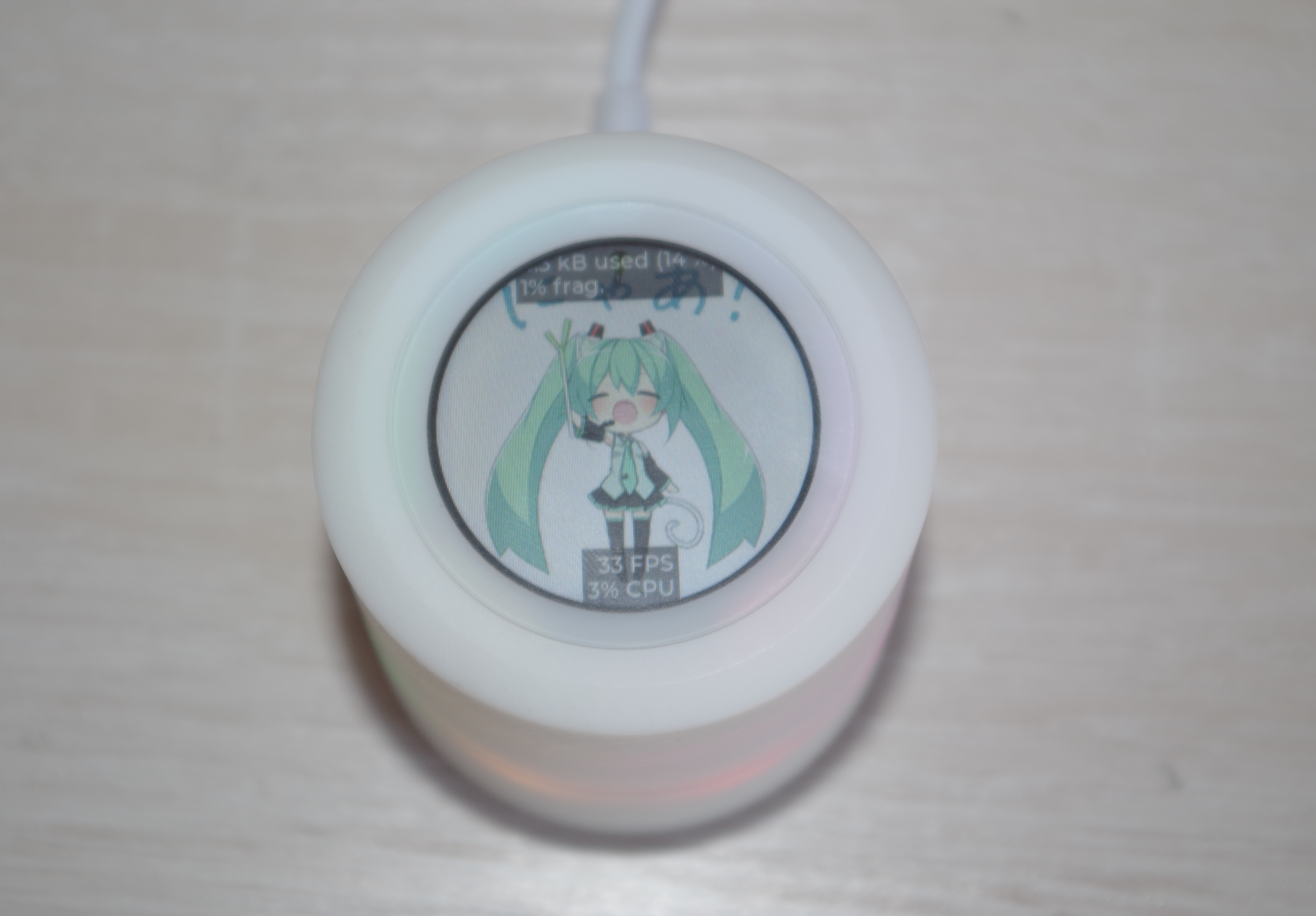
2. Pc performance monitor.
3. Wifi webserver implements picture modification.
7.Communication
816782369(Drive with CNC+SMT kit)
8.Thanks and Quotes
I am very grateful to Mr. Chong Er and JLC for their OSHWLab Stars, which allowed the project to be quickly iterated and implemented.
Designed by 45coll (from OSHWHub)
a:https://oshwhub.com/45coll/a2fff3c71f5d4de2b899c64b152d3da5
Design Drawing
 Empty
Empty
Comment