

 Completed
SpotWelder
PRO SpotWelder
License
:Public Domain
Description
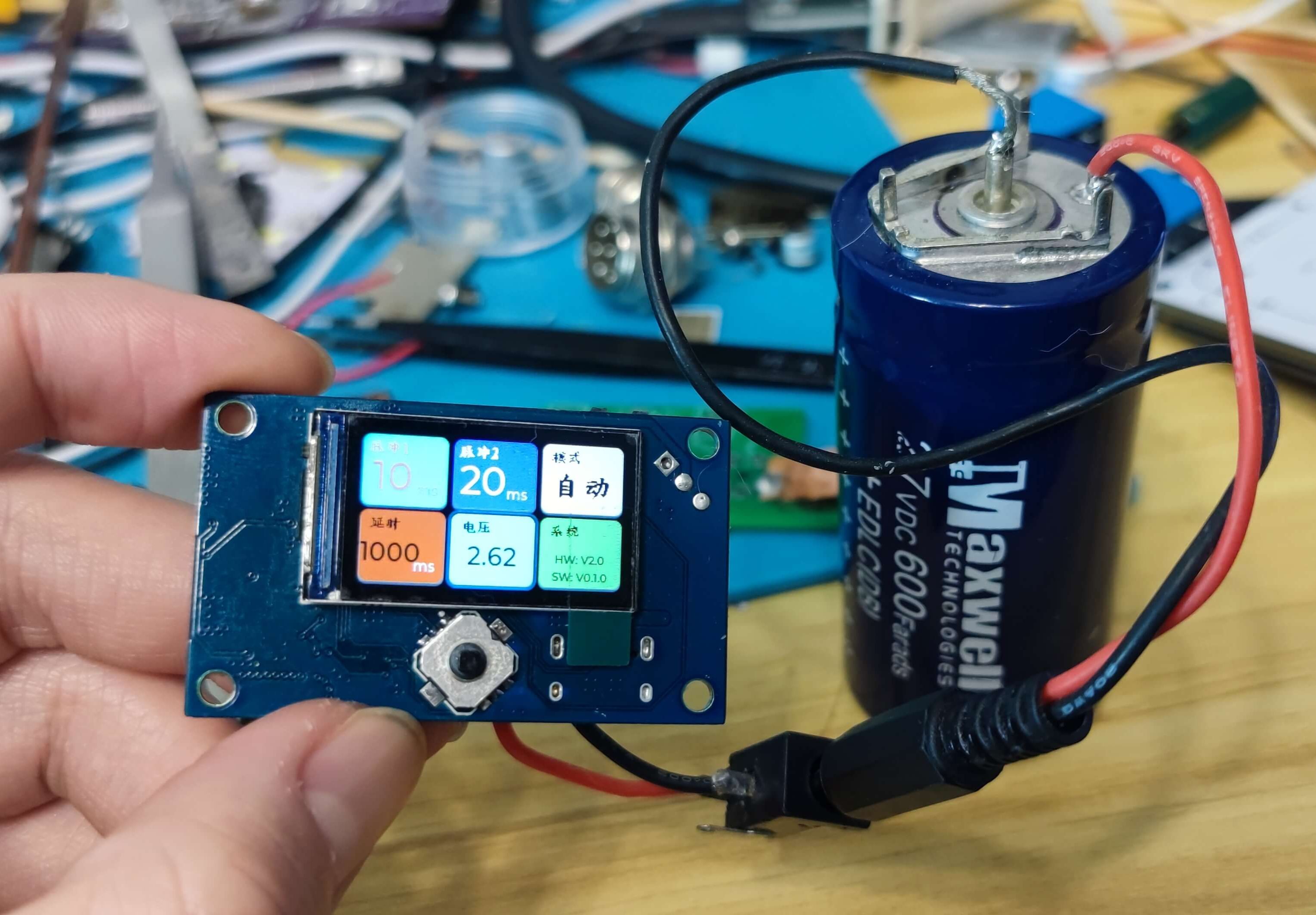
Handheld mini independent spot welding machine (the structural part is not completed)


Snail table equipped with large spot welding machine


Function support is as follows:
1. Supports 2~3 strings of supercapacitors.
2. Support PD fast charging protocol. Onboard 6A DCDC step-down circuit. Supports external DC port to input larger current power supply.
3. Onboard balancing charging, with a maximum balancing current of 0.5A. The default is 2.625V to enable balanced charging (the parameters can be changed by yourself).
4. Onboard 4A gate driver, turning on the mos faster.
5. The FPC cable interface is reserved for external independent control board, so that it can operate independently of the snail platform.

Driver board related issues
1. R33, R34, R21, R22, R3, and R4 are balancing resistors and will generate heat when balanced. Therefore, the bottoms of the six resistors can be bonded with silicone thermal conductive glue.
2. The SB4 and SB5 short circuit points (choose one of the two) determine whether the charging power supply connected to the DC socket is connected to the onboard DC-DC circuit or passes through the supercapacitor. SB4 is connected to DC-DC. At this time, the voltage of the connected power supply is 7~20V. SB5 is a pass-through supercapacitor, and the access voltage is equal to the capacitor charging voltage. In addition, only one TypeC and DC socket can be connected at any time.
3. The R70 resistor controls the constant current of the onboard DC-DC power supply. You can remove R70 if it is not used.
4. U4 is the onboard DC-DC power control core. It will get hot when charging, so you can attach a heat sink appropriately.
5. GND is the negative electrode of the series supercapacitor. C1+ is the positive electrode of the first supercapacitor in series. C2+ is the positive electrode of the second supercapacitor in series. C3+ is the positive electrode of the third supercapacitor in series (if there are only two series of supercapacitors, it will not be used). If the supercapacitor has two strings, please short-circuit SB1; if it has three strings, please short-circuit SB2 (you can only choose one of the two when SB1 and SB2 are short-circuited)
6. The wiring between the driver board and the MOS version uses XH2.54_3P co-directional wire. 5cm is enough.
7. The vias marked "Tin-filled holes" on the back need to be filled with tin to enhance the current flow capacity.

Structural Issues
It is best to solder the copper bars on the MOS board to the MOS board.
Properly use M6 screws to mechanically fix the MOS board and copper bus to prevent the copper from detaching due to strong pulling.
The driver board is fixed on the MOS board using M3*10 double-pass and same column.
Designed by ClimbSnail (from OSHWHub)
Design Drawing
 Empty
Empty
Comment