

 Completed
MRDK1A - 32MR_PLC Industrial Programmable Logic Controller
PRO MRDK1A - 32MR_PLC Industrial Programmable Logic Controller
License
:CC BY-NC-SA 4.0
Description

32-Channel programmable logic controller based on STM32F1 series MCU design
MCU programming software: keil 5
Ladder diagram programming software: Gxworks2
Open source license: CC-BY-NC-SA-4.0 (This product is only for PLC working principle, programming learning, teaching use, and is prohibited for any form of commercial use)
Basic parameters: Power supply: 220V-0.3A
Output mode: relay
Input range: 5~ 24V
Output touchpoint capacity: AC250V-5A DC310V-3A
Number of output units: 32 (IN: 16P---OUT: 16P)
Series product naming:

The default is relay output. If you need transistor or thyristor output, you can directly replace the mechanical relay with a solid-state relay, or redesign the output unit.
The main control uses the STM32F1 series MCU, which can port programs to other platforms or add and delete units. The selected MCU: RAM memory should not be less than 48K, and Flash memory should not be less than 256K.

Host peripherals and communication unit.

The main power supply (when selecting the inductor of L1, attention should be paid to the DCR value below 20mΩ). If it is higher than that, it will cause the DC-DC to generate a large amount of heat in the working state (which may affect the long-term stability).


IO unit circuit
Output drive principle: MCUIO > > Optocoupler isolation > > 2803 drive > > Relay
Input driver: 5~ 24V signal > > Optocoupler isolation > > MCUIO

PCB-3D

Shell


Laser sintered nylon shell

If used under harsh conditions, it is recommended to add a shielding cover to the control circuit to enhance its anti-interference ability under harsh conditions.


Sheet metal shell plate thickness should be 0.1~ 0.2mm JLC sheet metal minimum can only be 0.5mm, if 0.5mm plate thickness should be welded with the main board installation.
The back shell is fixed with reeds and C45 guide rails.
Spring: 0.6 * 4 * 15.


RTC clock battery.


Gxworks2 configuration instructions.
In Gxworks2 PLC model selection FX2N create project.

Communication selection: RS232 communication, and select the corresponding serial port.

PLC Test Procedure 1: Three Motor Sequential Start and Stop.

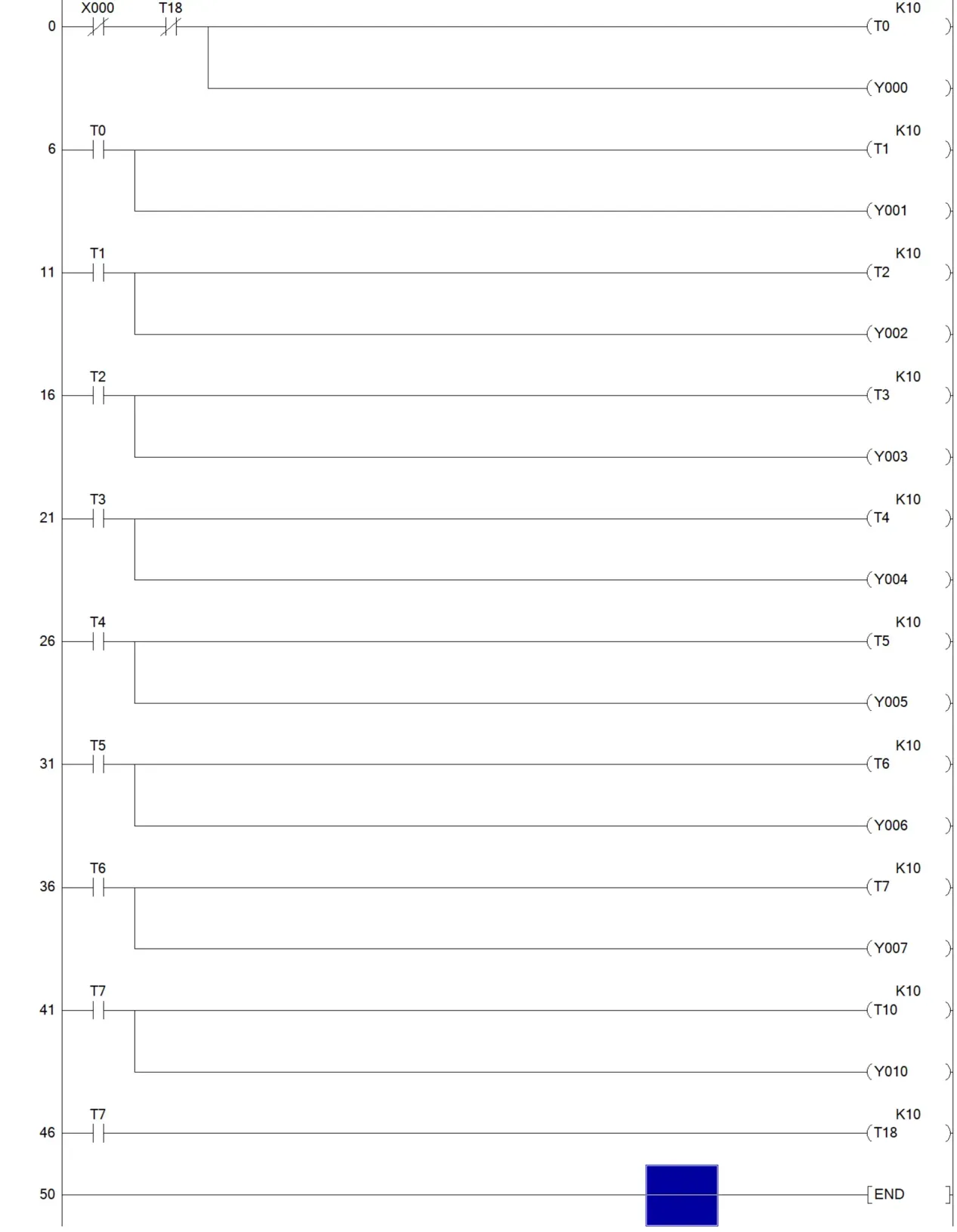
PLC test program 2: running light (delay 1s)
Test video: https://www.bilibili.com/video/BV144f3YcEp8/?vd_source=f2ecf6d07c56387a85d94b5338693a63
Program, shell, routine see engineering attachment


Designed by 模成Electron (from OSHWHub)
Link:https://oshwhub.com/dingcheng/mrdk1a-16mrplc-industrial-progra
Design Drawing
 Empty
Empty
Comment