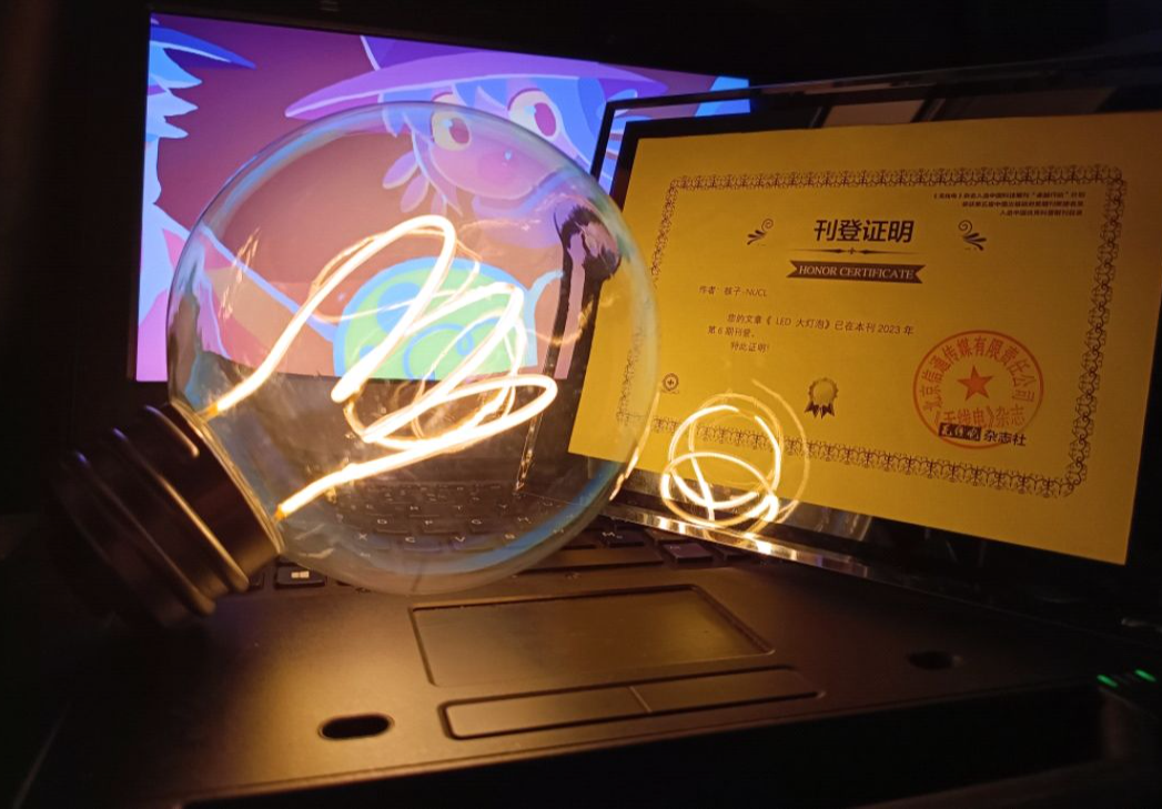
 Completed
Large LED Bulbs
PRO Large LED Bulbs
License
:GPL 3.0
Description
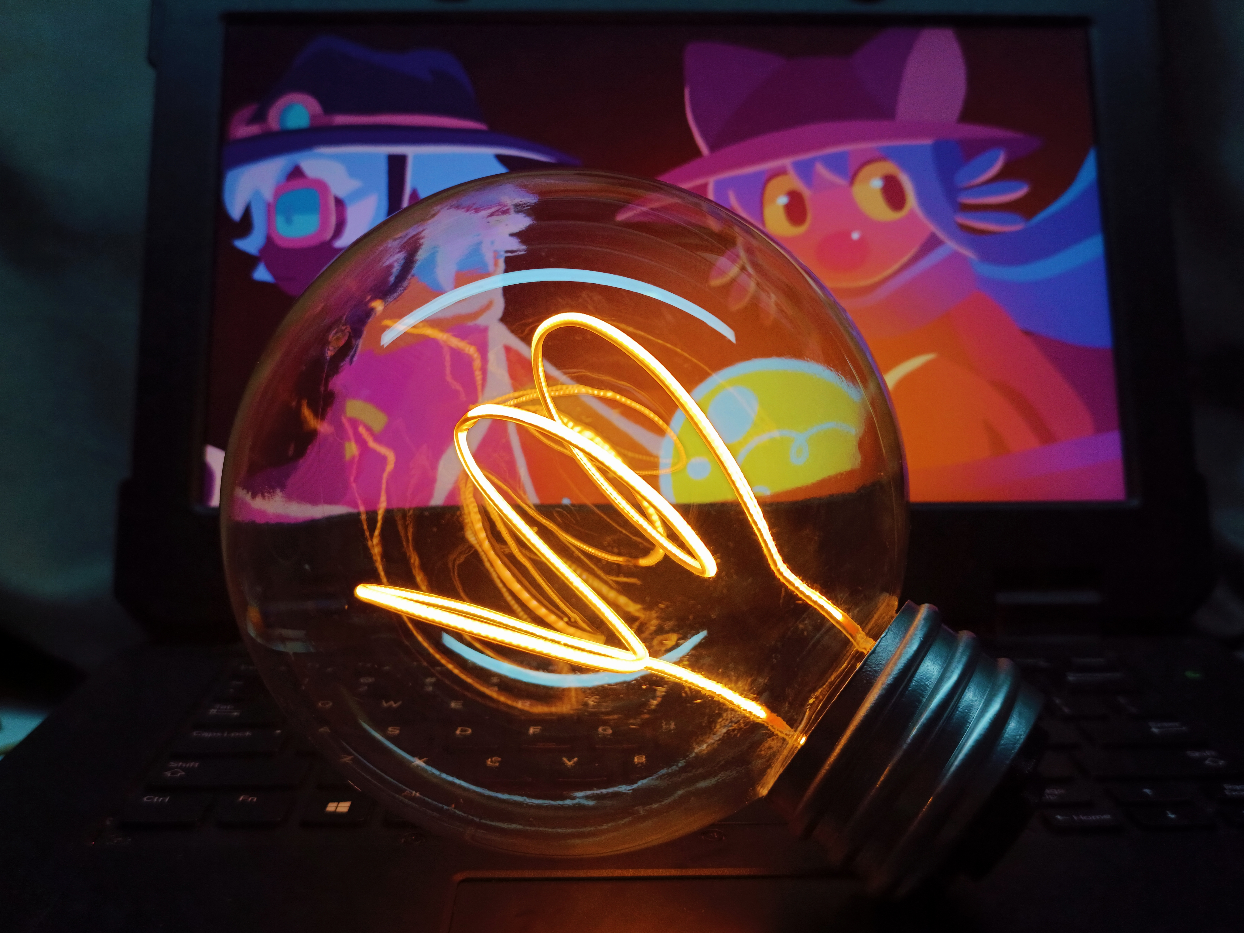
In February of this year, I played a game - OneShot. In the game, I was fascinated by the large light bulb that Niko was holding in his hand. So I decided to use my spare time to make a work that resembles the big light bulb in the game. After months of searching and verifying the solution, I finally made a large light bulb that I was quite satisfied with. I hope that this big bulb will bring joy and surprise to everyone.
Application scenarios: household lighting, handicrafts.
Function introduction: touch/proximity (light ball) sensing, touch (light tail) stepless dimming, Type-C charging.
As of July 7, 2023, I have updated the 2nd generation LED large bulb motherboard, which is more suitable for DIY production.
As of October 29, 2023, I have updated the 3D model of the 3rd generation LED bulb, which hides the radar module.
As of April 18, 2024, I have updated the PCB diagram of the 3rd generation LED bulb (the scheme has been verified)
The author recently received some feedback about users DIY the work themselves, and found some problems.
I will explain these problems one by one in this project, and optimize and supplement the tutorials of this project.
I have a set of kits for making this work on the shelves of a certain treasure, and if you are interested, you can search for the store: "Nuclear Studio" to find the store.
For study reasons, the store will sell goods after 6/10/24.
I have created a QQ electronic communication group, and I welcome all enthusiasts to join the group chat: 527972069
PS: This is my entry-level work.,It's been updated for a few days.,I found that the documents and circuit diagrams I did before were so bad.,It's a shame.
Design Scheme:
This work has the advantages of practicality, personalization, portability, energy saving and environmental protection. The production principle is simple and easy to understand, suitable for personal DIY.
This work is powered by a 3.7V polymer lithium-ion battery and charged by a TP4056 lithium-ion charge management chip.
This work has two functions, proximity sensing and touch sensing, and two light sensing methods can be selected by flipping a switch:
*A-Microwave Radar Touch/Proximity Sensing: Light up the bulb by touching or approaching the bulb. (Lamp brightness is the maximum brightness)
*B-Stepless dimming touch sensing: You can light up the bulb by touching the specified position of the lamp tail, and you can adjust the brightness of the bulb by touching it again.
Selected Materials:
Transparent housing: Regarding the lampshade, since the lampshade is custom-made, this type of lampshade cannot be found on the market. Here, I have put on the shelves of a certain treasure to make consumables parts.
Filament: The filament is made of flexible LED filament, which is formed by a special process. The lamp beads are arranged more densely, and compared with ordinary LED strips, the flexible LED filament emits uniform light and the filament diameter is small. It is suitable for the production of filament of this work. The filament is made of two 300mm long flexible LED filaments connected in parallel, plus enameled wire, steel wire, and heat shrinkable tube.
Lamp tail shell: The lamp tail shell is formed by light-curing printing, which requires black acrylic coating, electroplating self-spray paint, and varnish protective paint.
Filament fixing: This model has certain requirements for the flexibility and rigidity of the consumables. Whenever possible, FDM is used for printing molding. It can be printed with PLA, PETG and other materials.
Induction module: The induction module adopts Hilink's HLK-LD102 10GHz radar sensing module, which has a small sensing distance, and can customize the sensing parameters and working mode through the host computer.
Stepless dimming module: the chip adopts RH6618A, and the chip also has its own touch sensing.
Preparation of Materials:
Here is a table of the main materials used to make the work:
|
LED Large Bulbs DIY Material Table |
||
|
material |
quantity |
use |
|
The works of the circuit board |
1 |
Master control |
|
HLK-LD102 10G radar module |
1 |
Proximity sensing, non-contact sensing |
|
103030 1000mAh polymer lithium battery |
1 |
Power the control board |
|
USB to TTL module |
1 |
Configure the parameters of the radar module |
|
Width 20mm copper foil tape |
1 |
Touch sensing |
|
Length 300mm LED flexible filament |
2 |
Filament assembly |
|
0.8mm diameter steel wire |
1 |
|
|
2.5mm diameter transparent heat shrink tubing |
1 |
|
|
1mm diameter transparent heat shrink tubing |
2 |
|
|
0.3mm diameter enameled wire |
3 |
|
|
Filament holder (FDM printing required) |
1 |
Enclosure assembly |
|
Lamptail housing (requires light-curing printing) |
1 |
|
|
Painting kits (paints, inks, protective paints) |
1 |
|
|
PET lampshade (needs to be customized) |
1 |
|
|
Diameter 32mm circlip |
1 |
|
|
Hot melt adhesives |
1 |
Ancillary Materials |
|
Silicone oil |
1 |
|
|
adhesive tape |
1 |
|
|
Note: Some components and assemblies will be specifically added below. |
||
LED filament: This work requires two LED filaments with a length of 300mm and a color temperature of 2200K. The filament is purchased in a certain treasure, and the unit price is about 7 yuan.
It should be noted that the filament is very resistant to stretching, and it is easy to break if it is overstretched.

Silicone oil: used to lubricate the filament. Dimethicone oil is used here, as long as it acts as an insulating lubrication.

Copper foil tape: Use copper foil tape with a width of 20mm for touch sensing.

Radar module: HLK-LD102 10G radar module is used. Solder the ZH1.5mm-5pin cable to the radar module.
If the module is too long, you need to cut a part of the pad and cut off the PCB boards on both sides of the module without affecting the soldering.
Silkscreen definition on the radar module: V is VCC, G is GND, O is OUT, RB1 is RX, RB0 is TX.

USB to TTL module: A treasure can buy one for a few dollars. It's USB to TTL.
In order to facilitate the burning, I made an adapter board to connect the cables of different specifications.

Filament fixings and tail housings: Filament fixings are printed with FDM, while tail housings are molded with light-curing printing. The tail housing needs to be painted, painted, and coated with protective paint.

Circlip: 32mm metal circlip, needs to be operated with circlip pliers. The circlip is embedded in the filament holder to secure the filament.

Steel wire: 0.8mm diameter stainless steel wire is used, with moderate hardness and softness. It is recommended to use large pliers to cut the steel wire, if you use to cut the pins of the components, it is easy to scrap the pliers.
(The author's pliers have been scrapped 3 times, just because the steel wire was cut)

Design Principles:
Stepless dimming: Single-channel touch IC-RH6618 is adopted. Compared with the SGL8022W, the RH6618 has a higher PWM frequency and smoother dimming, which effectively improves the flicker problem.


RH6618A touch dimming is achieved by touching the TCH pins of the human body, and when the chip is working, the POUT pin outputs a PWM signal, which is connected to the NMOS tube gate to drive a higher current LED flexible filament.
The stepless dimming working mode is changed by controlling the high and low levels of the pins (MOD1, MOD2) of the control mode configuration. In the schematic diagram of the third-generation LED bulb, I discarded the two 0Ω resistors and directly suspended MOD1 and grounded MOD2 to configure the working mode.
MOD1 and MOD2 are high by default. When the high level is configured, it can be directly connected to the positive pole of the power supply, or the pin can be directly suspended, and the low level can be configured to connect the mode coordination pin to ground. Among them, TCH is a touch sensing pin, which can be inducted by touching the copper foil, and the copper foil can be pasted to the non-metallic sheet to achieve touch sensing.
In the figure, PADAR-POUT is the PWM signal input of the radar module.
The following is the output mode configuration table in the RH6618 data sheet:

Taking NO.2 as an example, we can configure the mode mode, which is stepless dimming without brightness memory, and fades into darkness without brightness memory when grounding MOD2 or connecting the positive pole of the power supply (VDD).
Lithium battery charging management:It adopts TP4056 lithium battery charging management chip. The chip has low cost, excellent performance and a wide range of applications.
When connected to a 5V (VCC) power supply, when the LED lights red, it indicates that the battery is charging. When the LED lights green, the battery is fully charged. Among them, BAT is connected to the positive electrode of lithium battery.

We can limit the current charged by changing the resistance (R8) next to the PROG pin: RPROG = 1200/IBAT (error ± 10%)
For example: RPROG=1200Ω IBAT=1000mA; RPROG=2400Ω IBAT=500mA ; RPROG=12000Ω IBAT=100mA .
Microwave Radar Module:
Don't! Again! Send me a private message! There is no! Programmed!!!!!!!
Engineering! Already! Written! It's clear!!And marked with markers and red letters!!!!
This module uses the HLK-LD102 10G microwave radar module. Data link: HLK-LD102 radar module data is based on the principle of Doppler radar, which can realize the detection of motion and micro-motion. The radar can support the modification of perception parameters.
About the radar module program code: This question is the most asked by the most people, the radar module information is downloaded from the official website of Hilink, which contains user instructions and the host computer. Download the host computer. Use the USB to TTL module to connect the radar module to the computer, and turn on the host computer to connect and edit. The official website provides detailed instructions for use, which are simple and easy to understand.

Here, we trigger the radar module by touching or approaching the light ball with our hands. I modified the control mode: 3 (the light gradually brightens up after the condition is triggered, and fades off when triggered again.) ); Block Time: 2000 (cannot be triggered again within 2000ms after triggering.) Repeated triggering in short periods of time is prevented. ); Threshold: 500 (The smaller the threshold, the more sensitive the trigger.) Distance: 255 (The higher the value, the greater the sensing range, the maximum value is 255.) )

Production process:
Once you've got the burning and preparation process done, it's time to start making.
The following are the materials required for the production of filament, the pin of the filament with hole is the positive pole, special attention needs to be paid when welding, the filament connection method is parallel, do not connect the positive electrode and the negative electrode together.
After the heat shrinkable tube is sleeved with the filament, heat the heat shrink at both ends, do not heat the whole, the overall heating and heat shrinkage may cause damage to the filament in the later stage.
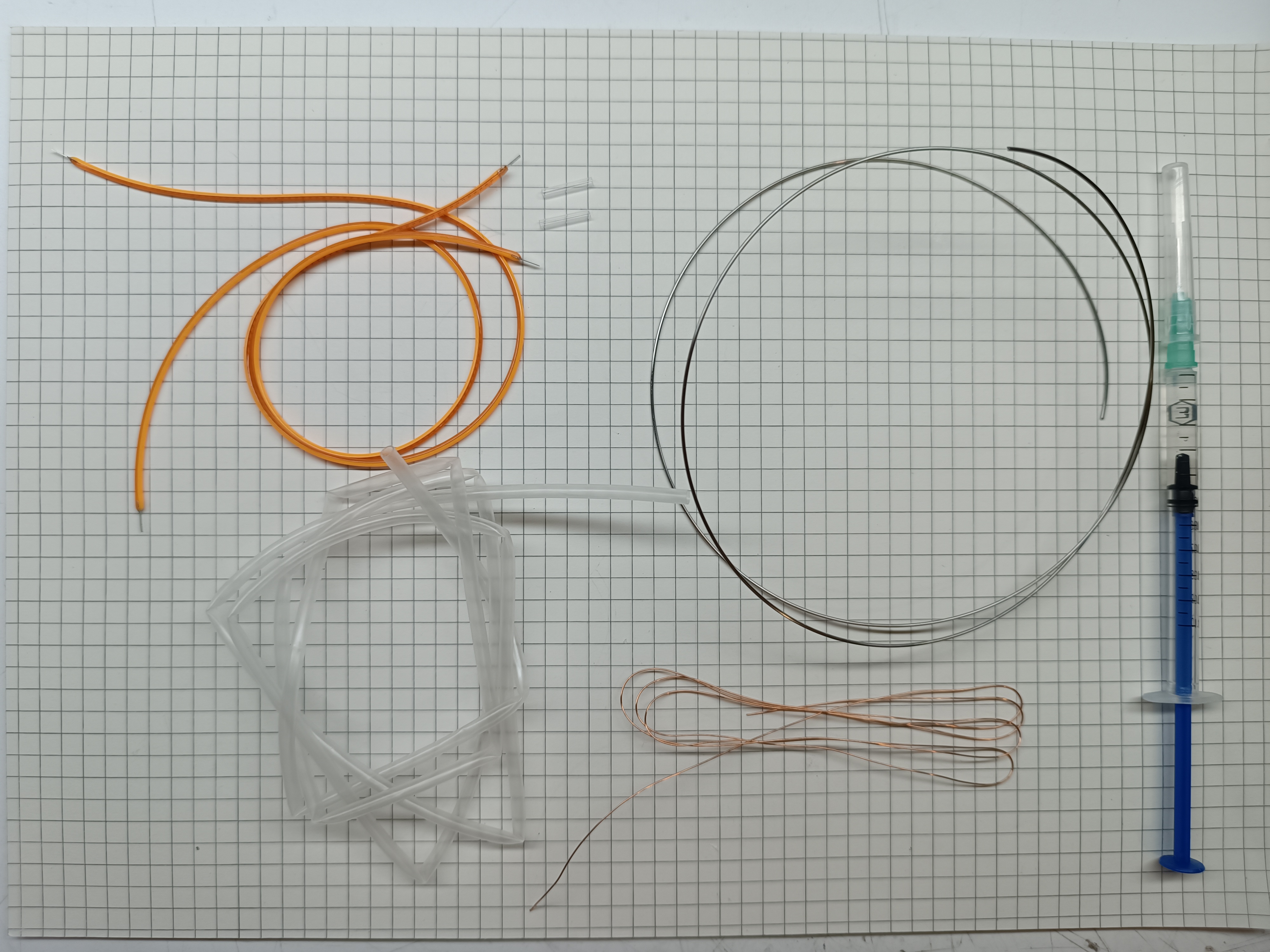
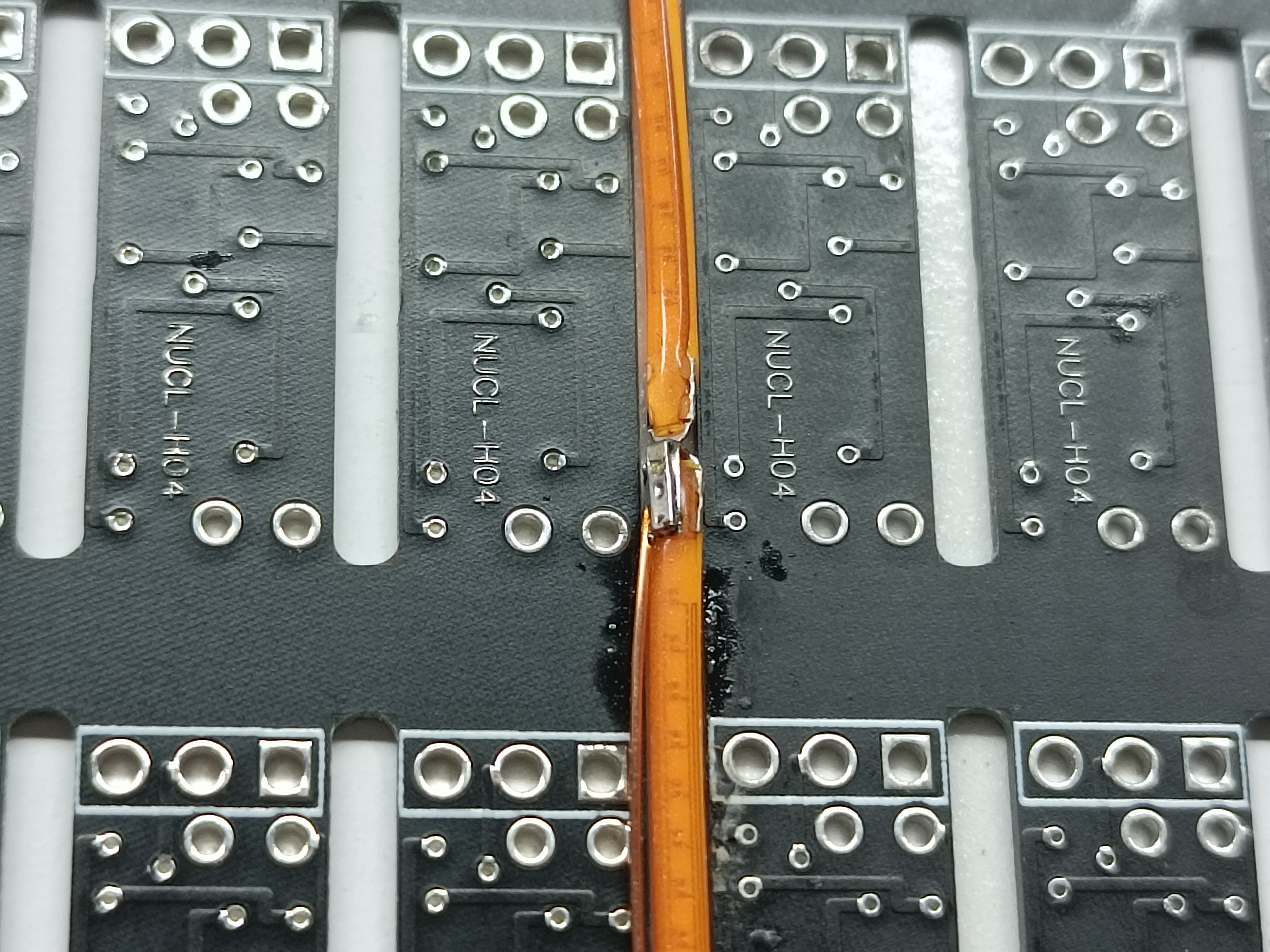
Attach the radar module to the filament fixing, and fix it with hot melt adhesive, and wait for the hot melt adhesive to solidify. Thread the semi-finished filament through the filament fixing. Then use pliers to bend the wire clamp of the semi-finished filament to increase the contact area of the hot melt adhesive. The wire and filament fixings are then covered with hot melt adhesive. After waiting for the hot melt adhesive to solidify, then use a soldering iron to solder the enameled wire and ZH1.5mm-2pin wire in the filament, and pay attention to the positive and negative poles of the filament with 3V power supply when soldering.

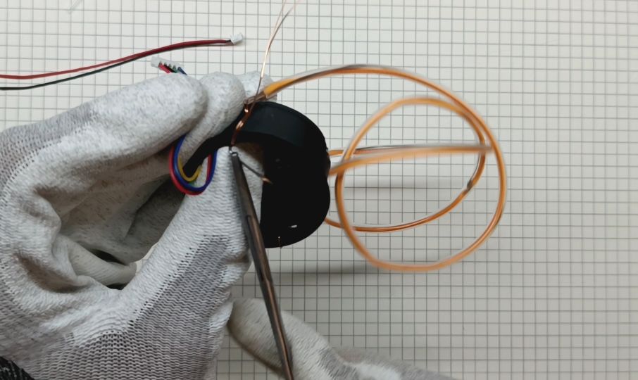
Insert the clamp into the filament mounting, secure the filament, and then apply hot melt adhesive.

Pinch the filament shape. Connect the accessories to the motherboard for testing.
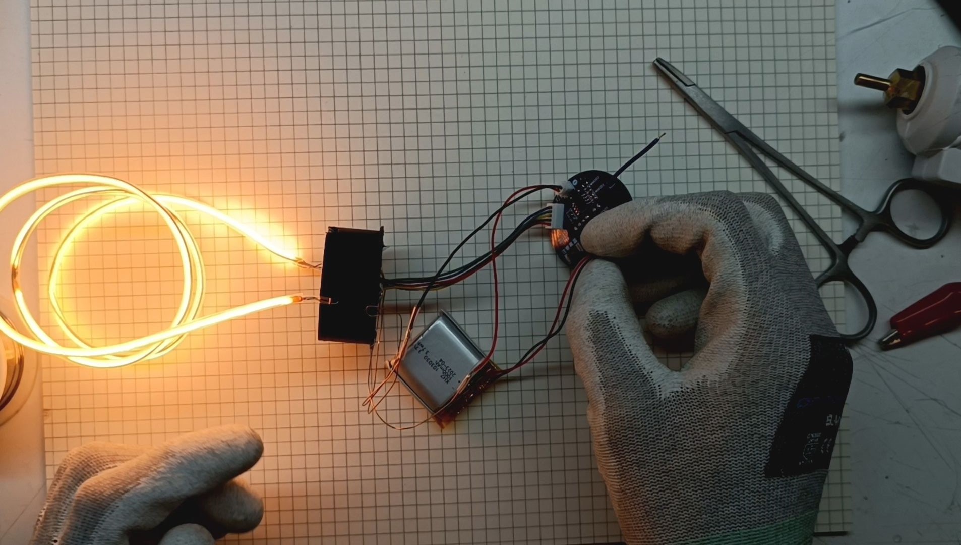
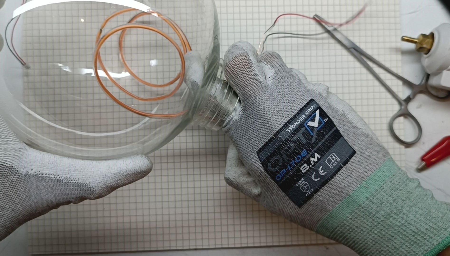
After the test function is normal, tuck the filament into the bulb and fine-tune the filament shape with your fingers.
This process requires a lot of patience and minimal adjustment of the filament to reduce the risk of filament damage.
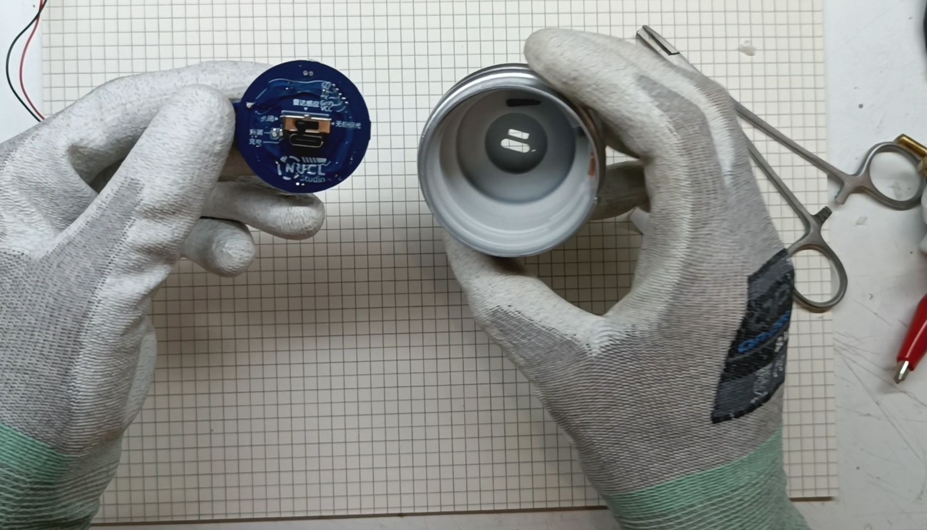
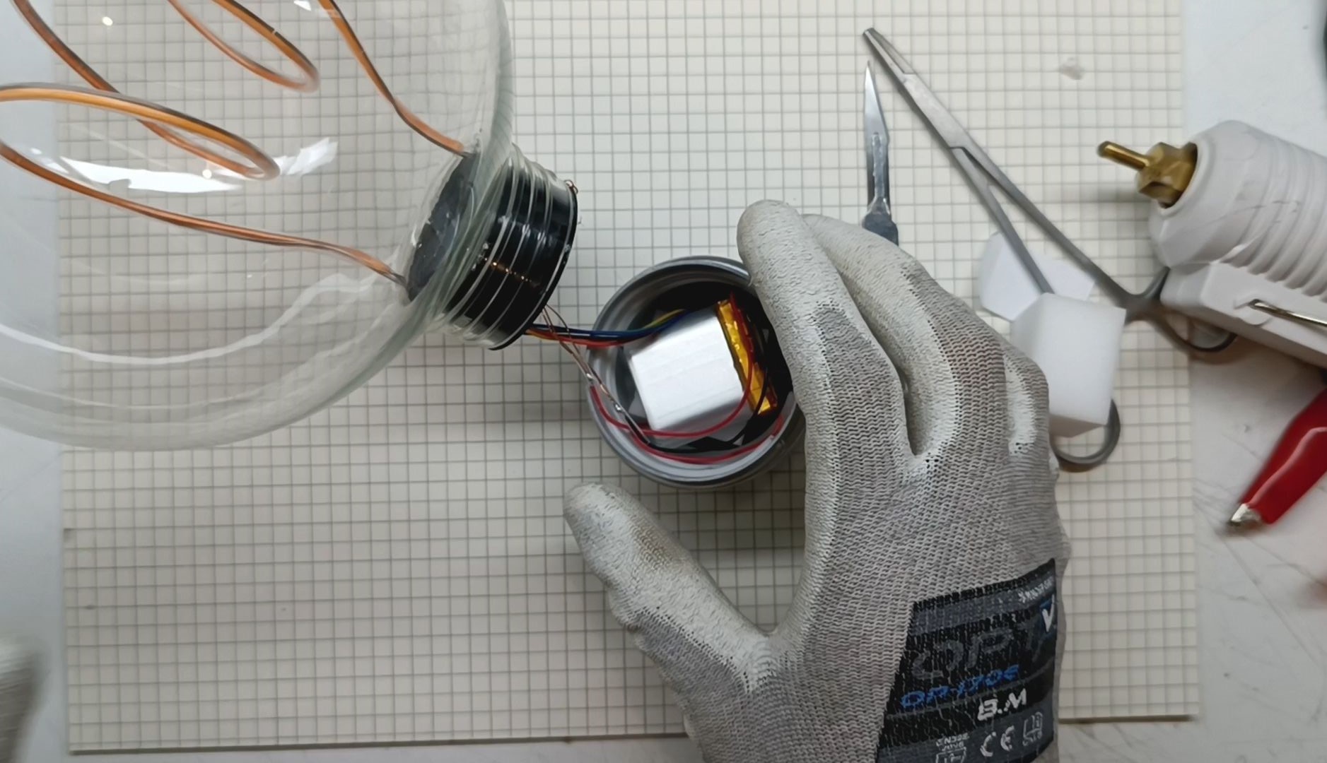
Apply hot melt glue to the back of the motherboard and secure the motherboard and case together while it is hot.
Attach copper foil to the inner wall of the lamp tail housing, and then connect the touch sensing wires and copper foil together.
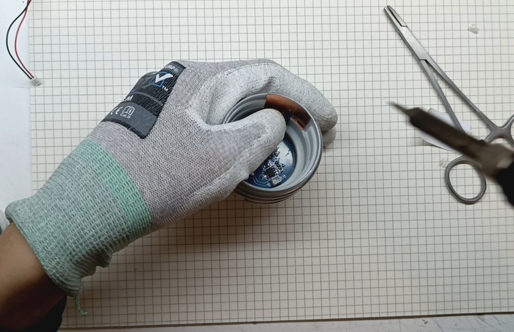
When connecting the fittings and screwing the housing, avoid the wires on the internal threads, and it is recommended to tie the wires all together with tape.
Before screwing, it is also necessary to rotate in the opposite direction for one time, so as to avoid the wire being twisted one more time and causing the circuit to break.
The internal space is relatively compact, and if you find that you have to use a lot of force when screwing, or you can't screw it, it is likely that the battery is stuck. It needs to be removed and reassembled.
Physical Display:

Design Considerations:
When designing a circuit, we should place all capacitors near the corresponding IC in order to better perform their role. For stepless dimming ICs, copper placements should be avoided as much as possible in the vicinity of them, especially TCH pins. In addition, we need to keep the surrounding traces at a distance from the TCH line. Avoid adverse interference with the stepless dimming IC.
Try to be patient when assembling, otherwise it may cause damage to the spare parts.
The detailed tutorial of the production can also be viewed on Bilibili: [LC Open Source Spark Project - Replica Game "OneShot" LED Large Light Bulb. 】
The author is going to take the college entrance examination, and his studies are relatively busy. Please note that updates and replies may be slower.
Designed by 核子-Nucleon (from OSHWHub)
Link:https://oshwhub.com/qxqpcb/fu-ke-you-hu-OneShot-Nikode-deng
Design Drawing
 The preview image was not generated, please save it again in the editor.
 Empty
Empty


Comment