

 Completed
Electric Flip Socket
PRO Electric Flip Socket
License
:GPL 3.0
Description
Electric Flip Socket
With the increasing number of charging devices around us, such as mobile phones, tablets, watches, headphones, mice, keyboards, desk lamps, e-cigarettes, game controllers, laptops, etc. The usage rate of sockets is gradually increasing, and the number of sockets is becoming more and more. As the number of sockets increases, the size of the sockets gradually increases, making them particularly bulky and troublesome in terms of appearance and portability. So I was wondering if I could design a very convenient and smart socket to meet the needs of life. Considering that most of my electronic devices are used on the desktop, if I combine the desktop with the socket, I can make Isn’t the hidden one very beautiful? Thinking of this, I opened a certain treasure, and sure enough I found a matching socket on it. It can be hidden under the table by flipping it over, but the price is really expensive. The cheapest one actually costs 700. As an electronics enthusiast, I absolutely cannot spend this money, so I had a bold idea to "make it myself".
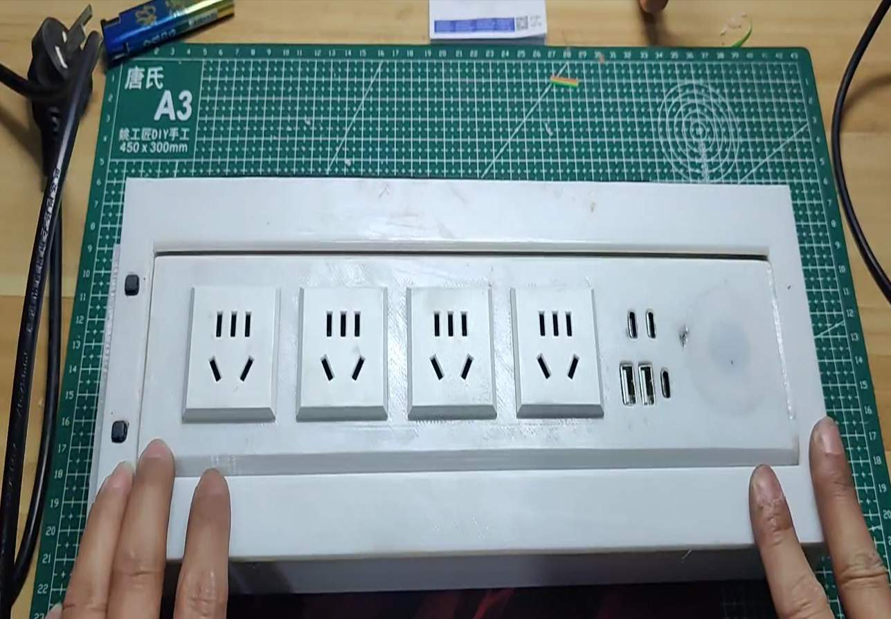
Since I don’t know what the internal structure of the socket is like, I can only imagine based on my own experience: flip function: use the servo; socket: you can buy ready-made PDU shift sockets online for assembly; add a few The USB interface is used to charge watches and game controllers; of course, the fast charging function of mobile phones is still needed; so I determined the function of the final socket: a four-way five-hole socket is used to meet the needs of some household appliances; two A USB charging interface, two TYPE-C charging interfaces, and a TYPE-c download interface (will be used later). Of course, the wireless charging function is a must.
I will list all the hardware in detail one by one, as shown in Figure 1.
|
3D printing |
||
|
serial number |
name |
quantity |
|
① |
Flip the outer bin -1 |
1 |
|
② |
Flip the outer bin -2 |
1 |
|
③ |
Flip inside compartment -1 |
1 |
|
⑤ |
Flip inside compartment -2 |
1 |
|
⑨ |
Cable clamp |
1 |
|
⑩ |
table fixing block |
1 |
|
⑪ |
Flip inside compartment -3 |
1 |
|
serial number |
name |
quantity |
|
⑥ |
Steering gear MG995-180 degrees |
1 |
|
⑦ |
Bearing 6805 (inner diameter: 25 outer diameter: 37 thickness 7 ) |
1 |
|
④ |
One five-hole socket (embedded card type) |
4 |
|
⑧ |
Servo matching connecting rod |
1 |
|
|
5m power cord |
1 |
|
|
Power adapter 220V to DC24V8A |
1 |

Figure 1
Step 1: Print all the 3D printed parts, and put the No. 7 "Bearing" into the round hole of the No. 1 "Flip Outer Chamber -1 ", as shown in Figure 2.

Figure 2
Step 2: Insert the protruding section of the No. 3 "Flip Socket Inner Chamber -1 " into the No. 7 "Bearing", as shown in Figure 3. After the installation is completed, as shown in Figure 4 .
 Figure 3

Figure 4
Step 3: Install No. 6 "Servo" and No. 5 " Flip Inner Chamber -2 " together and fix them with screws, as shown in Figure 5.

Figure 5
Step 4 : Hot-melt the screw hole on the opening side of the No. 3 "Flip Inner Chamber - 1 " nut M1.6*3*2.5 as shown in Figure 6 :

Figure 6

Figure 7
Step 5: Fix the assembled No. 5 " Flip Inner Bin -2 " and No. 3 "Flip Inner Bin -1 " together, as shown in Figure 7 .
Step 6: Install the PCB-USB board and wireless charging coil inside the No. 3 "Flip Inner Chamber -1 " and fix it with screws as shown in Figure 8 :
 Figure 8
Figure 9
Step 7: Lead out the four black wires on the PCB , the cables connected to the USB board, and the cables of the wireless charging coil, as shown in Figure 9 ( PCB board details are as follows:)

Step 8: Fix the circuit board to No. 11 " Flip Inner Compartment -3 " and lead the four live wires to the four socket holes, as shown in Figure 10 :
 Figure 10
Figure 11
Step 9: Prepare two wires as the five-hole socket (neutral wire, ground wire) and peel and divide them, as shown in Figure 11.
Step 10: Connect and fix the socket with the black wire (black connects to the L terminal of the socket), as shown in Figure 12.

Figure 12

Figure 13
Step 11: Pass the prepared two sets of wires through the holes in parallel together with the black (live wire), and connect them to the N terminal and bottom line terminal of the socket respectively, as shown in Figure 13 (the first one near the bearing direction) You can leave the socket unplugged for now because the power cord needs to be connected in the next step)
Step 12: Prepare a power cord ( 1.5㎣ ) as shown in Figure 14 , and pass it through the bearing hole as shown in Figure 15. Connect the N neutral wire and ground wire to the terminal of the first socket respectively , as shown in Figure 16.
 Figure 14
Figure 15

Figure 16
Step 13: Weld the live wire of the power cord to the circuit board. At the same time, if the DC terminal socket is welded to the DC24 , you need to unplug the power cord first, insert it into the power adapter terminal, and then insert the power cord, otherwise the adapter terminal The head is too big to fit into the bearing hole. If there is no soldering, you can solder the wires provided by the power adapter on the PCB and lead them out, as shown in Figure 17.
 Figure 17
Figure 18
Step 14: Connect the PCB and USB board connection wires one by one. Don’t forget to connect the servo and wireless charging coil, and also lead out the wires of the two buttons as shown in Figure 18.
Step 15: Fix No. 11 " Flip Inner Chamber -3 " to the PCB board as shown in Figure 19 and install and fix it with No. 3 "Flip Inner Chamber -1 " as shown in Figure 20.
 Figure 19
Figure20
Step 16: Lead the wire of the button from the side through the button hole as shown in Figure 21 , and solder the button as shown in Figure 22.
 Figure21
 Figure22
Step 17: Fix the button in the groove, straighten the wires in the groove as shown in Figure 23 , install two M3 hot-melt nuts in the two screw holes below , and press the No. 9 " cable ” Installed on the side, as shown in Figure 24.
 Figure 23
Figure 24
Step 18: Install the No. 2 " Flip Outer Chamber -2 " on one side of the servo as shown in Figure 25. Install the No. 8 " Servo Connecting Rod " in the groove and fix it with screws as shown in Figure 26 , and install the M3 hot-melt nut on the bottom .
 Figure 25
Figure 26
At this point the entire electric flip socket is completely assembled.

Next is the software program part:
#include
#include
#define server_ip "bemfa.com" //Baffa cloud server address default
#define server_port "8344" //Server port number
#define wifi_name "*******" //The name of your home WIFI
#define wifi_password "*****"//Your own WIFI password
String UID = "*******"; //Private Key Usage Period Register a cloud server. The cloud server used in this program is Bafa CloudBafa Technology & Bafa Cloud - Bafa Equipment Cloud - Bafa iot Cloud Platform (bemfa.com)
//Theme Name
String TOPIC1 = "1fzcz006"; //Toggle on Overflow Bit
String TOPIC2 = "2fzcz006"; //1 relay control
String TOPIC3 = "3fzcz006"; //2 relay control
const int KEY = 2; //Define a key to control the steering gear rotation
const int JiDianQi1 = 14;
const int JiDianQi2 = 12;
Servo myservo;
#define MAX_PACKETSIZE 512 //Maximum bytes
#define KEEPALIVEATIME 60*1000 //Set the heartbeat value to 60s
WiFiClient TCPclient; //tcp client initialization by default
String TcpClient_Buff = ""; //Initialization string that accepts data sent by the server
unsigned int TcpClient_BuffIndex = 0;
unsigned long TcpClient_preTick = 0;
unsigned long preHeartTick = 0; //heartbeat
unsigned long preTCPStartTick = 0; //connect
bool preTCPConnected = false;
void doWiFiTick();
void startSTA();
void doTCPClientTick();
void startTCPClient();
void sendtoTCPServer(String p);
int servoState = HIGH; //Current status of steering gear
int buttonState ; //Button current status
int lastButtonState = LOW;//Status of the last button
bool servoTurnedOn = false;
int pos = 0;
unsigned long lastDebounceTime = 0;
unsigned long debounceDelay = 50;
int angle;
int val=180;
int val1=0;
/*
*Send data to the TCP server
*/
void sendtoTCPServer(String p){
if (!TCPclient.connected())
{
Serial.println("Client is not readly");//The client did not read the file
return;
}
TCPclient.print(p);
preHeartTick = millis();//Heartbeat timing starts and data needs to be sent every 60 seconds
}
/*
*Initializes the connection to the server
*/
void startTCPClient(){
if(TCPclient.connect(server_ip, atoi(server_port))){
Serial.print("\nConnected to server:");
Serial.printf("%s:%d\r\n",server_ip,atoi(server_port));
String tcpTemp=""; //initialization string
tcpTemp = "cmd=1&uid="+UID+"&topic="+TOPIC1+","+TOPIC2+","+TOPIC3+"\r\n"; //Build subscription instruction
sendtoTCPServer(tcpTemp); //Send subscribe instruction
tcpTemp="";//clear
/*
//If you need to subscribe to multiple topics, you can send them cmd=1&uid=xxxxxxxxxxxxxxxxxxxxxxx&topic=xxx1,xxx2,xxx3,xxx4\r\n
Tutorial: https://bbs.bemfa.com/64
*/
preTCPConnected = true;
TCPclient.setNoDelay(true);
}
else{
Serial.print("Failed connected to server:");
Serial.println(server_ip);
TCPclient.stop();
preTCPConnected = false;
}
preTCPStartTick = millis();
}
//Check the data sending heartbeat
void doTCPClientTick(){
int but;
//Check whether the connection is disconnected, and then reconnect the connection
if(WiFi.status() != WL_CONNECTED) return;
if (!TCPclient.connected()) {//Disconnect and reconnect
if(preTCPConnected == true){
preTCPConnected = false;
preTCPStartTick = millis();
Serial.println();
Serial.println("TCP Client disconnected.");
TCPclient.stop();
}
else if(millis() - preTCPStartTick > 1*1000)//reconnect
startTCPClient();
}
else
{
if (TCPclient.available()) {//Received Data
char c =TCPclient.read();
TcpClient_Buff +=c;
TcpClient_BuffIndex++;
TcpClient_preTick = millis();
if(TcpClient_BuffIndex>=MAX_PACKETSIZE - 1){
TcpClient_BuffIndex = MAX_PACKETSIZE-2;
TcpClient_preTick = TcpClient_preTick - 200;
}
}
if(millis() - preHeartTick >= KEEPALIVEATIME){//keeps the heartbeat
preHeartTick = millis();
Serial.println("--Keep alive:");
sendtoTCPServer("ping\r\n"); //Send heartbeat, the command needs to end \r\n, see the access document
}
}
if((TcpClient_Buff.length() >= 1) && (millis() - TcpClient_preTick>=200))
{
TCPclient.flush();
Serial.print("Rev string: ");
TcpClient_Buff.trim(); //Drop the first space
Serial.println(TcpClient_Buff); //Print the received message
String getTopic = "";
String getMsg = "";
if(TcpClient_Buff.length() > 15){//Note that TcpClient_Buff is just a String and is initialized at the beginning of the String TcpClient_Buff = "";
//At this time, you will receive a push command, which is about cmd=2&uid=xxx&topic=light002&msg=off
int topicIndex = TcpClient_Buff.indexOf("&topic=")+7; //c language string search, find &topic= location, and move 7 bits, do not understand can Baidu c language string search
int msgIndex = TcpClient_Buff.indexOf("&msg=");//c language string search, find &msg= location
getTopic = TcpClient_Buff.substring(topicIndex,msgIndex);//c language string interception, interception to topic, do not understand the c language string interception
getMsg = TcpClient_Buff.substring(msgIndex+5);//c language string interception, interception message
Serial.print("topic:------");
Serial.println(getTopic); //Print the captured topic value
Serial.print("msg:--------");
Serial.println(getMsg); //Print the captured message value
}
if(getTopic == TOPIC1){//When the flip function is triggered
if(getMsg == "on"){
servoTurnedOn = true;
myservo.write(180);
Serial.println("overturn");
}else if(getMsg == "off"){
servoTurnedOn = false;
myservo.write(0);
Serial.println("switch back");
}
}else if(getTopic == TOPIC2){ //When relay one triggers
if(getMsg == "on"){
digitalWrite(JiDianQi1, HIGH);
Serial.println("Relay 1 on");
}else if(getMsg == "off"){
digitalWrite(JiDianQi1, LOW);
Serial.println("Relay 1 off");
}
}else if(getTopic == TOPIC3){ //When the second relay triggers
if(getMsg == "on"){
digitalWrite(JiDianQi2, HIGH);
Serial.println("Relay 2 on");
}else if(getMsg == "off"){
digitalWrite(JiDianQi2, LOW);
Serial.println("Relay 2 off");
}
}
TcpClient_Buff="";
TcpClient_BuffIndex = 0;
}
}
void startSTA(){
WiFi.disconnect();
WiFi.mode(WIFI_STA);
WiFi.begin(wifi_name, wifi_password);
}
//WiFiTick Check whether the wifi needs to be initialized, check whether the wifi is connected, and start the TCP Client if the connection is successful
void doWiFiTick(){
static bool startSTAFlag = false;// Start STA mode
static bool taskStarted = false; //Task started
static uint32_t lastWiFiCheckTick = 0;//Finally WiFi check click
if (!startSTAFlag) {
startSTAFlag = true;
startSTA();
}
//Fails to connect for 1s and reconnects
if ( WiFi.status() != WL_CONNECTED ) {
if (millis() - lastWiFiCheckTick > 1000) {
lastWiFiCheckTick = millis();
}
}
//连接成功建立
else {
if (taskStarted == false) {
taskStarted = true;
Serial.print("\r\nGet IP Address: ");
Serial.println(WiFi.localIP());
startTCPClient();
}
}
}
void setup() {
Serial.begin(115200);
pinMode(KEY, INPUT_PULLUP);
pinMode(JiDianQi1, OUTPUT);
pinMode(JiDianQi2, OUTPUT);
digitalWrite(JiDianQi1, LOW);
digitalWrite(JiDianQi2, LOW);
myservo.attach(13,500,2450);
myservo.write(0);
}
void KEY_1(){
int reading = digitalRead(KEY);
if(reading != lastButtonState){//The state read this time is not equal to the last time, indicating that the button has changed
lastDebounceTime = millis();//Current conversion amplitude time
}
if((millis() - lastDebounceTime) > debounceDelay){
if(reading != buttonState){
buttonState = reading;
if(buttonState == HIGH){
// servoState = !servoState;
servoTurnedOn = !servoTurnedOn;
}
}
}
if (servoTurnedOn){
myservo.write(0);
}else{
myservo.write(180);
}
/*if (servoState == HIGH){
myservo.write(0);
}
if(servoState == LOW){
myservo.write(180);
}*/
lastButtonState = reading;
}
void loop() {
doWiFiTick();
doTCPClientTick();
KEY_1();
}
This program is very simple, the user only needs to modify these few items:
#define wifi_name "*******" //The name of your home WIFI
#define wifi_password "*****"//Your own WIFI password
String UID = "*******"; //Private Key Usage Period Register a cloud server. The cloud server used in this program is Bafa CloudBafa Technology & Bafa Cloud - Bafa Equipment Cloud - Bafa iot Cloud Platform (bemfa.com)

Copy your registered account private key to the program String UID = " ******* ";
After the modification is completed, enter Baffa Cloud and create a theme as shown in Figure 27.

Figure 27
Notice:
Private key representation: String UID in the program = " ******* "; //User private key
The new topic in Baffa Cloud represents: String TOPIC1 = "1fzcz006"; //Flip control
String TOPIC2 = "2fzcz006"; //Relay No. 1 control
String TOPIC3 = "3fzcz006"; //Relay No. 2 control
The three devices must correspond one-to-one with the names in the program;
Step 2: Install Baffa Cloud APP , Figure 28. After installation and login, the three themes just created will be displayed on the switch device as shown in Figure 29 ; (You can download it from the official website, or scan the QR code)

Figure 28
 Figure 29
 Figure 30
Figure 31
Step 3: Open the APP and test to see if there is any response when flipping the socket. If it can be used normally, enter the "Mijia APP " to associate and synchronize the device, open the Mijia APP , click "My" and find "Connect to other platforms" as shown in Figure 30 . Click "Add" and I have already added it here. Search or find "Baffa Cloud" to add it. After the addition is completed, you can use Xiaoai Audio Control!

Figure 32
Note: I have made some long-term designs on this socket;
For example: 1. Because I often travel on business, I brought out the ESP8266 download interface to facilitate future program upgrades.
2. I reserved two buttons on the socket, one of which controls the flipping of the socket, and the other one can be customized according to needs. I originally planned to control the lighting in the horizontal version, but I ran out of time and I had to go to work again.
Designed by zhaoyiyi1 (from OSHWHub)
Link:https://oshwhub.com/zhaoyiyi1/dian-dong-fan-zhuai-cha-zuo
Design Drawing
 Empty
Empty
Comment