

 Completed
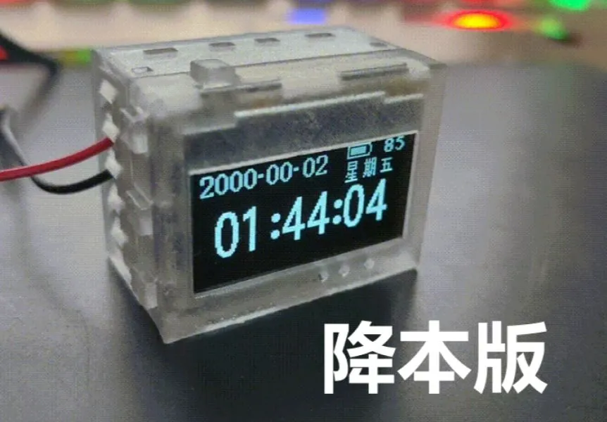
[Always on for 24 days] Low power consumption - Mini desktop clock (cost-reduced version)
PRO [Always on for 24 days] Low power consumption - Mini desktop clock (cost-reduced version)
License
:CC BY-NC-SA 4.0
Description

Splash screen and smearing compress video and photography problems, but it doesn't actually look like this.
The actual effect can be referred to the original GIF (below) or video.

Update plan
√ 2024.06.27 release project, open source PCB [control board 4.0.4 cost reduction] [power board 2.8.5 cost reduction]
Upload open source project + source code (without alarm clock)
Release firmware 20240627A upgrade program
Open source shell STL, STP files
√ 2024.07.03 upload Taobao BOM, Lichuang Mall BOM
⚫ 2024.07.10 upload SOP operation manual (not updated, because no one saw a copy, it was shelved)
Cost
LCSC order: 200 yuan + = 150 + 10 (postage) + 30 (Taobao to buy batteries, OLED, RTC batteries, vibration switches, FFC lines) + 12 (3D shell + shipping)
Taobao order: 120 yuan + = 109 + 12 (3D shell + shipping)
Find resentment authors to take materials: 70 yuan = 52 (shared number and freight) + 9 (shared freight 3D shell) + 10 freight.
Departure
The third batch of 16 clocks in this project is being produced, too many people asked before, they were too busy, the project did not dare to update, the message did not dare to reply, and did not dare to make a sound
Because many people leave messages or private messages that I want, and the welding difficulty of this project is relatively large, I am very emo to see that the small partners in the group are not successful, if you really want to private message me (after reading the following note), 63 free shipping loss of shell money to make a friend, but the delivery period may have to wait a little longer, the author needs some time to make a black slave.
Project display video
Function demonstration and running power consumption display of this version: https://www.bilibili.com/video/BV1hZ421g7mz
Project description
This project is based on [always bright 24 days] low power consumption - mini desktop clock https://oshwhub.com/yq-qvq/low-power-consumption-for-24-days-desktop-clock project cost reduction and improvement, reduce costs, the current batch cost is about 50 yuan +, a single production cost will rise because postage can not be shared.
This project is based on the legendary 32-bit 51 microcontroller STC32G12K128 chip as the main control of the low-power desktop clock, with an average power consumption of 1.7378mA (6.8593mW) in TV mode (factory default setting) at 5V 255 brightness, and can run for about 24 days. Equipped with RTC, temperature and humidity, magnetic strength, acceleration, air pressure, and light intensity sensors for development.
Attention
The power supply of this project is a soft pack lithium battery. Please pay attention to safety when using it. Do not leave when charging to avoid physical damage to the battery, avoid overcharging and overdischarging short circuit, and avoid being placed in harsh environments such as high temperature or low temperature.
Screen burn-in problem
This project uses an OLED screen. If a certain pixel is lit for a long time, it will produce light attenuation, resulting in a "mark" on the screen. The following picture shows the burn-in situation after 6-7 months of use. The horizontal line is the camera shooting problem. You can see that there will be marks in the places that are often displayed, but the normal display time interface is almost invisible, unless you enter the menu or pure white picture.
Therefore, the screen is basically a consumable, and it can be replaced every year or a year and a half. If you mind, please do not copy or buy it.

Project change point
- OLED screen communication has changed from the original SPI to the I8080 bus.
- Logic power supply reduced from 2.8V to 2.7V.
- The chip resistor and capacitor have been replaced from 0402 to 0603, touch switch, FFC seat, RTC battery, all of which have been replaced. The capacitors are unified using MLCC, the PCB is rearranged, the pins are adjusted, the reset button is placed below the screen, and all underlying drivers are correspondingly modified.
- The voltage reduction chip has been changed from TPS62740DSSR to ETA3425S2F.
- Removed the fuse, the lithium battery protection chip ME4211AM6, and the protection board that relies entirely on the soft pack battery for protection.
- Remove the 4K square wave generating circuit and replace it with a single-chip PWM port direct drive to adjust the tone and volume.
- Remove CH340 and replace it with USB direct download.
- RTC adds packaging reservation, compatible with DS3231MZ.
- The light intensity meter has been changed from the original BH1745 to OPT3001.
- Shell redesign.
- MCU changed from STC32F12K54 to STC32G12K128. Although the speed is reduced, the flash is doubled, solving the problem of 32F being full.
- Cancel the OLED contrast current reference resistor, use the internal reference, but keep the pads.
- Fix the problem that applying for long waiting tasks in the program framework will cause blockage.
Project hardware resources
● Controller: STC32G12K128
1.3 inch OLED: SSD1315
Temperature and humidity meter: SHT40
● Barometer: SPL-06
RTC: INS5699 (reserved DS3231MZ package)
Light intensity meter: OPT3001
Magnetometer + Accelerometer: BMC050
● Buzzer
● Vibration switch
Button X5: +, -, OK, Exit, Reset
Project history
-
Start project ideation.
-
Proofing the power management board of version 2.0, soldering and testing.
-
Proofing version 2.0 core board, welding and testing.
-
Proofing iteration 2.0 version of the power management board, and soldering, testing.
-
Proofing the 2.0 version sensor board, welding and testing.
-
Proofing iterative 2.0 version of the core board, and soldering, testing.
-
Finish code writing
-
Proofing iterative 2.0 version of the core board, and soldering, testing.
-
Proofing iterative 2.0 version of the core board, and soldering, testing.
-
Started conceiving a low-power UI framework and used the development version for program foundation framework verification (where the dream began).
-
Sample 4.0 power board (new design), solder and test.
-
Proofing iteration 4.0 power board, welding, testing.
-
Proofing 4.0 control board (fusion 2.0 core board + 2.0 sensor board), welding, programming, testing.
-
Start designing, verifying, and finishing. Optimize the writing of programs such as entry and exit of the Ren account service stack, fast batch loading, main menu, secondary menu, and tertiary menu.
-
Start reading the English manual and write about sensor drivers.
-
Addicted to MC with friends.
-
Proofing iteration 4.0 power board, welding, testing.
-
Proofing iteration 4.0 power board, welding, testing.
-
Proofing iteration 4.0 power board (Yutai solution), welding, testing.
-
Proofing iteration 4.0 power board (Texas Instruments solution), welding, testing.
-
Proofing iteration 4.0 power board (Texas Instruments Scheme 2), soldering, testing.
-
Proofing iteration 4.0 power board V2.8.4 (Texas Instruments solution), soldering, testing.
-
Published in the Lichuang Open Source Community.
-
Proofing iteration 4.0 control board (I8080 bus scheme), welding, programming, testing.
-
Proofing iteration 4.0 power board V2.8.5, and soldering, testing.
-
Proofing iteration 4.0 control board V4.04 (SPI scheme), welding, programming, testing.
-
Proofing iteration 4.0 control board (I8080 bus scheme 2), welding, programming, testing.
-
New design 4.0 power board V2.8.5 (cost reduction), soldered and tested.
-
Iterative design of 4.0 power board V2.8.5 (cost reduction 2), and soldering and testing.
-
New design 4.0 control board V4.0.4 (cost reduction I8080 bus solution), and welding, program writing, testing.
-
Attempting to fix the issue of blocking caused by long waiting tasks in the program framework, testing, and no exceptions have occurred so far.
Power consumption
Tested using a CC meter with factory initial settings (OLED 5V 255 brightness, battery supply 3.84V, reduced version battery supply 3.94V, but automatic dimming off)
5V full brightness can last for 22 days, and if automatic dimming is turned on, it can last longer, up to 24 days or more.

UI display
Main menu (scrolling 3.94V 2.5mA):

Secondary menu (scrolling 3.94V 4.3mA):

Three-level menu:

TV mode (clock display interface):

TV mode (environmental display interface):

TV mode (power display interface):

Hibernation screen display mode:

Compass UI:

UI operation logic:

Low-power thinking
Friends familiar with PC devices should know that when our computers are idle, their power consumption is generally low because the CPU is down-clocked and in an "idle" state. Similarly, when reducing device power consumption, most people will adopt a down-clocking strategy. Many friends will ask me when they see me using a 30M main frequency: why not down-clocking?
Blindly reducing the frequency regardless of the situation will increase the power consumption of the equipment. The following figure tests the operating current of the STC32G12K128 microcontroller at various frequencies.

Here I tested the time required for the microcontroller to run 65535 times while (i--) at various frequencies. This is to prove that the time required for the microcontroller to process fixed tasks is inversely proportional to the main frequency. The 35M main frequency is 7 times that of the 5M main frequency, so the time required for processing tasks at the 5M main frequency should also be 7 times that of processing tasks at the 35M main frequency. In fact, this is also the case: 79200/11340 = 6.984
Software introduction
The software part, some of the underlying configuration using the STC manufacturer's sample code, OLED initialization reference Taobao attached code, inverse triangle function Atan CORDIC algorithm reference Redstone circuit bar code, the rest are self-developed, the program block diagram is as follows, using the task number stack + task waiting time stack for task reservation and execution, the middle of the waiting time into the power mode for transition.

The reason why it can save power so much is that the MCU does not do unnecessary things. It only runs when there is a task and sleeps at other times. When I was working on the first and second generation clocks, I found that the MCU often delays when executing tasks. For example, when scrolling numbers, it needs to translate 32 pixels 32 times. After each translation, there is a 6-millisecond interval before the next translation can be executed. At this time, the idle running time is 31x6 = 186ms, which is very fatal. If it refreshes once a second, 18.6% of the time is wasted waiting. For example, after sending a measurement command to the sensor, it needs to wait for a period of time to read the measured value, which also needs to be waited for.

In order to solve the problem of MCU slack off while waiting, MCU can enter power-down mode while waiting, thereby reducing power consumption
But this also has to face a new problem, that is, how does the MCU know when it will wake up? Because after the MCU enters power-down mode, the main clock stops, and it really falls asleep. How to know when it will wake up for work next becomes a problem
To address this issue, we can use a power-off wake-up timer, similar to how a worker can schedule an alarm clock. By setting the power-off wake-up timer time, we can control the MCU to wake up at the specified time after going to sleep, and then we can go further, for example, by shifting 32 pixels, we can set 31 alarms
Therefore, I introduced two arrays, one is the "sleep time array" and the other is the "task number array" (each bit represents a task), and the values of the two arrays correspond one-to-one. For example, to perform a 32-pixel translation, I would first reserve 32 tasks in the "sleep time array" and "task number array", as shown in the figure below.

Each time the MCU detects the values in the arrays "Sleep Time Array" [0] and "Task Number Array" [0], if they are not equal to 0, the values in the "Sleep Time Array" [0] are loaded into the power-off wake-up register for sleep, and then matched with the corresponding tasks based on the values in the "Task Number Array" [0] after waking up. After the task is completed, the values of the entire array move one bit to the left. When the values in the "Sleep Time Array" [0] and "Task Number Array" [0] are detected as 0, it means that the UI refresh task has been completed, the power-off wake-up register is closed, and the task is completely put into sleep, waiting for external key interruption to wake up the task.
However, there is not only one OLED screen refresh task in the project. For the sensor measurement waiting task, in order to ensure timeliness as much as possible, it is impossible to measure after the UI refresh is completed. Of course, we hope to achieve both. At this time, we need to write an insertion algorithm to insert the task into the task queue. For example, insert a pressure measurement task ("task number array" bit1 = 1) into the queue, which needs to wait for 15ms (6 + 6 + 3) and insert it into the queue shown in the figure below. It can be seen that when the values cannot coincide, the queue needs to be interrupted to insert the values. 3 is bit0 and bit1 is 1.

For example, on the basis of the above, inserting a pressure measurement task into the queue requires waiting for 12ms and inserting it into the queue shown in the figure below. It can be seen that when the values overlap, there is no need to interrupt the queue to insert the values. Only the bit corresponding to the task number needs to be added.

Based on the previous description, we know that the microcontroller does not constantly refresh the UI animation. There must be a certain interval between each pixel movement, otherwise it will move too fast. For example, in the main A La Carte model, three 32X32 icons will be displayed, with a screen length of 128 and a 16-pixel interval between them. Therefore, to complete a scroll, 48 pixels need to be translated, which is 48 times. If we wait for 6ms between each movement, it will take 282ms to complete a translation (excluding other execution times). If the microcontroller has no other work, then it is idling. Therefore, we will wait for the idling time and use sleep instead to reduce power consumption. At this time, it is necessary to push the UI refresh tasks (task number 0x0001) with 48 intervals and the interval time distribution of 6ms into the task number stack and task waiting time stack, which will be processed by the task sleep waiting module. Then, the microcontroller will wake up 48 times from sleep according to the interval of 6ms in the following time, and execute the UI refresh task once each time.
The following pictures show the data collected from the test PCB. The testing environment consists of a power board and a test main board (only soldering FFC seats, MCU, and buttons). The test access points are at the output ends of the battery.
Since the MCU power supply is provided by a buck of 2.7V, the actual 2.7V current is best converted by 1.4, of course, the battery is the ultimate power supply, and there is nothing wrong with using the original data source.
While (1) testing, simulating the full operation of the microcontroller, it can be seen that the current is about 7mA.

Main menu scrolling test, move the main menu UI every 1-2 seconds, you can see that the average current is about 1mA, zooming in can be seen, the current is 48 spaced spikes, indicating that the microcontroller intermittently works 48 times, completes 48 pixel movements, and then continues to sleep.


The scrolling test of the secondary menu shows that the main menu UI moves once every 1-2 seconds. It can be seen that the average current is around 2.9mA. When zoomed in, it can be seen that the current is 24 spaced spikes, indicating that the microcontroller works intermittently for 24 times, completes 24 pixel movements, and then continues to sleep. Because there are more things to calculate than the main menu movement, the pulse width of the current spike is larger, so it consumes more power.


This proves that the designed low-power UI architecture meets the original intention of the design. It only works when there is a task, and there is almost no delay in the entire program, avoiding the idling of the microcontroller and improving efficiency.
In the previous code, there was a serious bug in the framework, which was the queue-cutting algorithm. Even if it was inserted, the sub-module waiting for the task to sleep would not accept it and would not terminate the sleep of the current task. It would be blocked until the end of the current task. This caused the entire system to be blocked when waiting for some tasks with long appointment times. For example, after turning on the light control, it is necessary to obtain ambient light data every second. After each measurement, the reading will take 200mS. If you are currently in the menu interface and waiting for sensor data to be read, pressing the button will require waiting for the current appointment waiting time to complete before the UI can be scrolled. The macro performance is that there will be occasional lag after pressing the button. The correct effect should be that after pressing the button, if the sub-module waiting for the task to sleep is sleeping for other tasks, it needs to be aborted, the remaining time should be read back and filled into the task waiting time stack stack top, and then the task should be cut in line according to the interrupt source. After discovering this bug before, no matter how to fix it, it was not normal. However, on the early morning of June 24, 2024, I didn't give up and casually changed it. Surprisingly, it was fixed. So far, no abnormalities have been found in the test.
Main hardware introduction
MCU
The MCU used in this design is the legendary 32-bit 51 STC32G12K128. Since other series of microcontrollers cannot be used, only this model can be selected. The maximum frequency is 35M, and the maximum stable frequency of this project is 30M. If it exceeds, it will randomly restart inexplicably. This problem has troubled me for two weeks.
The power consumption is about 310uA/MHz, and the sleep test is about 2 uA. There is a hardware problem with the edge triggering in the power-down mode when the IO mouth is disconnected. Triggering one may be linked to another, which is difficult to hold.
The power supply is powered by a 3.7V 1000mA soft pack lithium battery.
Main circuit power supply
MCU, sensors, buzzers, and OLED logic are powered by ETA3425 DC-DC synchronous rectification buck, with a power supply voltage set to 2.7V. This voltage is limited by the need to charge the RTC battery, so it cannot be lowered too low.

OLED display power supply
OLED's own charge pump efficiency is extremely poor, it is recommended to use DC-DC boost, and synchronous rectification boost is not recommended, because the efficiency is less than 80%
The power supply for OLED display is provided by MT3608L DC-DC asynchronous rectifier boost, with optional power supply voltages of 5V, 6V, 7V, and 8V. The OLEDV1 (open drain) and OLEDV2 (open drain) pins are switched by MCU control
MT9700 is a limited viewership of the chip to prevent output short circuit
OLEDV1 1 OLEDV2 1 5V
OLEDV1 0 OLEDV2 1 6V
OLEDV1 1 OLEDV2 0 7V
OLEDV1 0 OLEDV2 0 8V
OLEDV1 (quasi-bidirectional) 1 OLEDV2 (quasi-bidirectional) 1 13V + prohibition, originally had isolation MOS, but later removed the cost.

| MT3608L (ripple 72mV) 10uf | ||||||
| Output voltage (V) | Output current (mA) | Output power (mW) | Input voltage (V) | Input current (mA) | Input power (mW) | Efficiency |
| 5.018 | 1.521 | 7.630 | 3.873 | 2.230 | 8.637 | 88.35% |
| 4.986 | 3.030 | 15.108 | 3.873 | 4.360 | 16.886 | 89.47% |
| 5.037 | 156.250 | 787.031 | 3.740 | 247.000 | 923.780 | 85.20% |
Lithium battery charging
The lithium battery is charged by ME4059ASPG-N, using DC-DC synchronous rectification step-down for charging, the charging current is about 550mA, which can greatly reduce the temperature rise caused by linear charging, and reserve control pins EN_2 and GHRG.
EN_2 is the ME4059ASPG-N enable pin, which can briefly turn off the enable when measuring the battery power during charging to obtain the true battery voltage.
GHRG is the charging status indicator port, which can determine the battery status and whether there is a battery.

Lithium battery protection
Completely relying on the battery's built-in protection board, without reserving protective device pads, the cost is reduced.
Lithium battery charging current detection
The INA181A2IDBVT chip provides 50x differential amplification, and the sampling resistor is placed on the low side to prevent leakage (placing it on the high side will generate a leakage current of about 11uA).

Just check the open source schematic for the rest.
Current feature introduction
Standard mode
- Burn-in protection
- Time display
- Temperature and humidity pressure
- Power status
- Hour reporting
- Settings
Sleep mode
- Time display
- Temperature and humidity pressure
- Power status
- Hour reporting
- Deep sleep
- Hibernation screen display
- Settings
Environmental information
- Temperature
- Humidity
- Air pressure
- Light intensity
Brightness settings
- Screen brightness
- Voltage level
- Automatic regulation
- UI Dynamics
- UI static
- Extremely dark mode
- TV static
- Linked voltage
- Luminance magnification
Compass
Level ruler
Time setting
- Seconds
- Points
- Time
- Week
- Day
- Month
- Year
- Settings
- Seconds
- Points
- Time
- Day
- Month
- Off on Saturday
- Off on Sundays
- Alarm clock duration
- Switch
- Button sound
- Sound length
- Main switch
- Tone adjustment
- Volume adjustment
- External power supply
- Internal power supply
- Supply voltage
- Charging current
- Remaining power
- Life protection (currently no function)
- Save parameters
- Anti-accidental touch (no function yet)
- 12-Hour system (no function yet)
- Screen flip (no function yet)
- Hibernation plan (no function yet)
- Start hibernation (no function yet)
- End sleep (no function yet)
- Main control model
- Thermohygrometer
- Barometer
- Light intensity meter
- Accelerometer
- Magnetometer
- Clock chip
- Screen controller
- Number of keys
- Version number
- Machine model
- Author
- Sensor
- Temperature compensation
- Humidity compensation
- Air pressure compensation
- ADC adjustment
Structure introduction
Re-model the shell, change the reset button to the bottom of the screen, press the screen to reset, the assembly is a bit difficult, and the operation manual will be released later for reference 3D printing uses JLC's light-cured, semi-transparent resin.

Designed by 御坂美琴我老婆 (from OSHWHub)
Link:https://oshwhub.com/yq-qvq/low-power-consumption-for-24-day
Design Drawing
 Empty
Empty
Comment