

 Ongoing
Power Multiplexer (TPS2121)
STDPower Multiplexer (TPS2121)
413
0
0
1
Mode:Full
License
:MIT License
Creation time:2025-02-21 06:27:09Update time:2025-02-24 02:40:59
Description
Need to supply your PCB with multiple power inputs, but want control over which to prioritize, want to ensure no backfeeding and all as efficiently as possible?
This is a power multiplexer based on the Texas Instruments TPS2121 IC. As configured, it'll take two inputs (a USB and a secondary source such as a 2C LiPo battery) and choose which one should be routed out.
Current features include:
- Operating range: 2.8v to 22v
- Absolute maximum input voltage of 24v
- Undervoltage lockout at 2.5v, helps ensure safety of LiPo batteries that can be damaged if drained too much.
- 500mA max output as configured, though this is only because of the LDO I'm currently using. The TPS2121 itself can support up to 4.5A
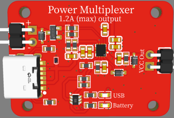
- Two power inputs (left) a USB 2.0 and a secondary connection. As configured it's assumed that the secondary (top left) connection will be 7.2v LiPo battery
- Two power outputs (right).
- The top right connection labeled VCC is the raw output of the multiplexer and is intended to be used for testing
- The bottom right connection is the output of a 3.3v LDO. The LDO is now required in thsi design, and can be omitted, but has been included for load testing
- Preference given to the USB if connected, even if the voltage on the battery is higher. This is to avoid draining the battery unnecessarily
- Battery connection is labeled with + and - but includes reverse polarity protection, just in case you accidentally wire it in backwards.
- Overvoltage protection on the battery connection set at 10v. Above 10v the battery input is disconnected and returns when voltage goes to 10v or below. This can be changed in your application by adjusting the values of the R203 and R204 resistors.
- Undervoltage protection on the USB connection set to 4.5v. Below 4.5v the USB input is connected and power is sourced from the battery (if connected). This can be changed in your application by adjusting the values of the R201 and R202 resistors.
- Status LEDs indicate which power source is being used - useful in testing but can be omitted
- RED = USB Powered
- Yellow = Battery Powered
- Pads on bottom for USB power and GND to support testing, can be omitted in your design
- Schottky diode added to TPS2121 to provide reverse polarity protection for the IC and anything connected. This diode as a forward voltage of 0.6v so technically the resistors on PR1 and OV2 should be adjusted according, however, the chosen tolerances didn't make it necessary.
- 6V 2A resettable fuse on USB line for overcurrent protection. Likely overkill for this project but included to test with another in mind.
Manufacturing Notes:
- Created with JLCPCB assembly intended, so all components reference parts available at JLCPCB. Whereever possible basic components were chosen to reduce mfg costs - mainly resistors and capacitors.
- 2-layer board with GND pours on top and bottom
Constructive comments and recommendations welcome.
Note: as of 2/22/25 this board has not yet been tested. I'm currently double-checking everything and preparing to send to MFG. Will update this page accordingly after testing.
Design Drawing
BOM
 Clone
CloneAdd to Album
0
0
Share
Report
Project Members
Followers0|Likes0
Related projects
 Empty
Empty
Comment