

 Completed
PULPY_F405_FC
License
:TAPR Open Hardware License
Description
🛠️ Custom Flight Controller for INAV 🚀
This FC (Flight Controller) was developed as an open-source playground for drone pilots, and although that’s the main objective for now, please note that untested modifications can make your drone behave unpredictably, so if you don’t exactly know what you are doing, please take it with a grain of salt.
I'm designing a custom flight controller (FC) for my drone project - it’s my first time building both a drone and a flight controller - and this FC is INAV-compatible, built around the STM32F405RGT6 MCU while also supporting GD32F405RGT6 and AT32F435 alternatives for flexibility.
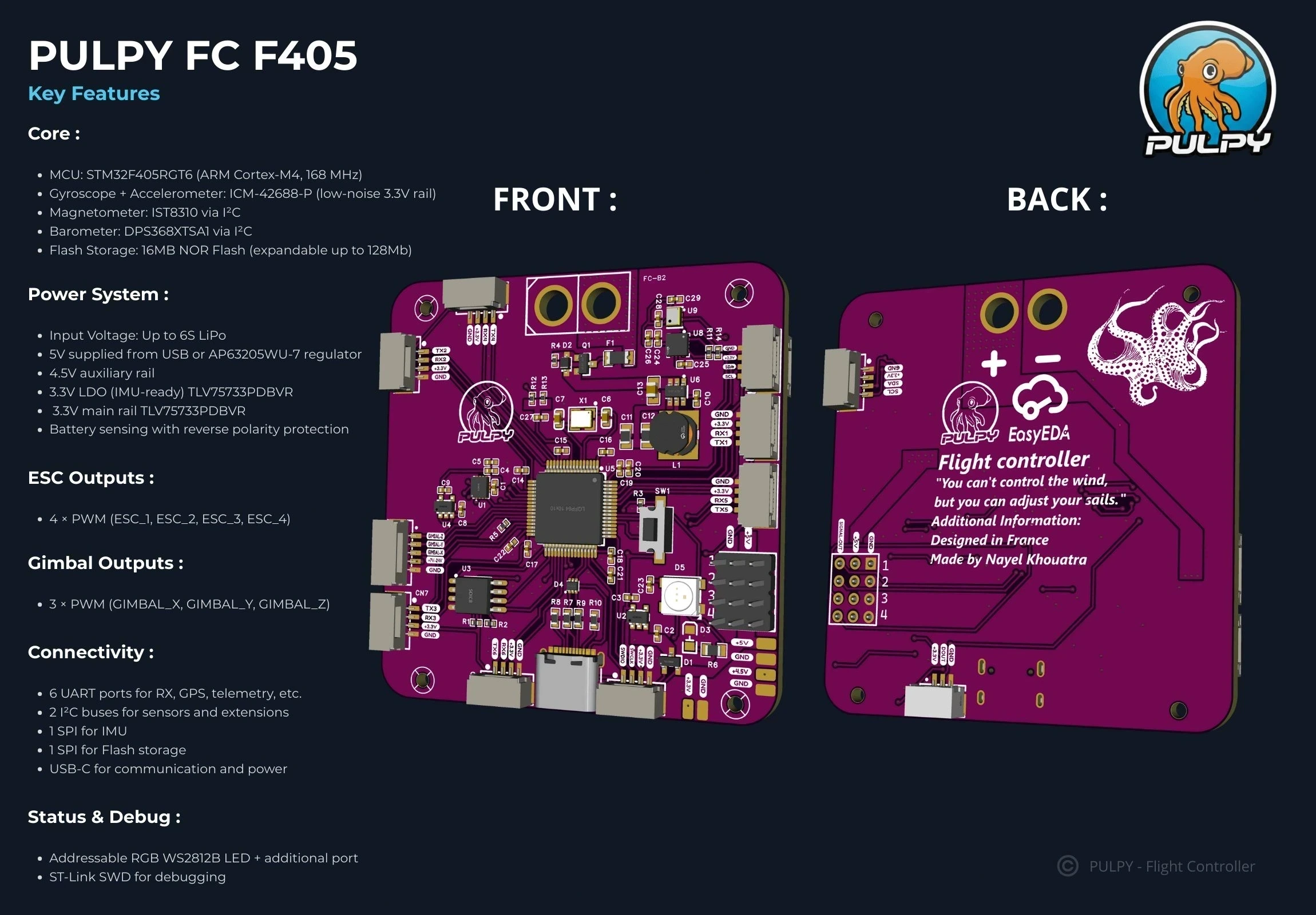
🔑 Key Features
Core
- MCU: STM32F405RGT6 (ARM Cortex-M4, 168 MHz)
- Gyroscope + Accelerometer: ICM-42688-P (low-noise 3.3V rail)
- Magnetometer: IST8310 via I²C
- Barometer: DPS368XTSA1 via I²C
- Flash Storage: 16 MB NOR Flash (expandable up to 128 Mb)
Power System
- Input Voltage: Up to 6S LiPo
- 5V: Supplied from USB or AP63205WU-7 regulator
- 4.5V auxiliary rail
- 3.3V LDOs:
- TLV75733PDBVR dedicated for IMU
- TLV75733PDBVR for the main sensor rail
- Battery sensing with reverse polarity protection
ESC Outputs
- 4 × PWM (ESC_1, ESC_2, ESC_3, ESC_4)
Gimbal Outputs
- 3 × PWM (GIMBAL_X, GIMBAL_Y, GIMBAL_Z)
Connectivity
- 6 × UART ports for RX, GPS, telemetry, etc.
- 2 × I²C buses for sensors and extensions
- 1 × SPI for IMU
- 1 × SPI for Flash storage
- USB-C for communication and power
Status & Debug
- Addressable RGB WS2812B LED + additional port
- ST-Link SWD header for debugging
🔹 First Design
The first design looks more like a development board with external connectors (SPI, I2C, UART) to test sensors individually. All functions were tested and working ✅ except the addressable LED, which didn’t light up ❌. Its main purpose was to serve as a flexible platform for testing components before integration.
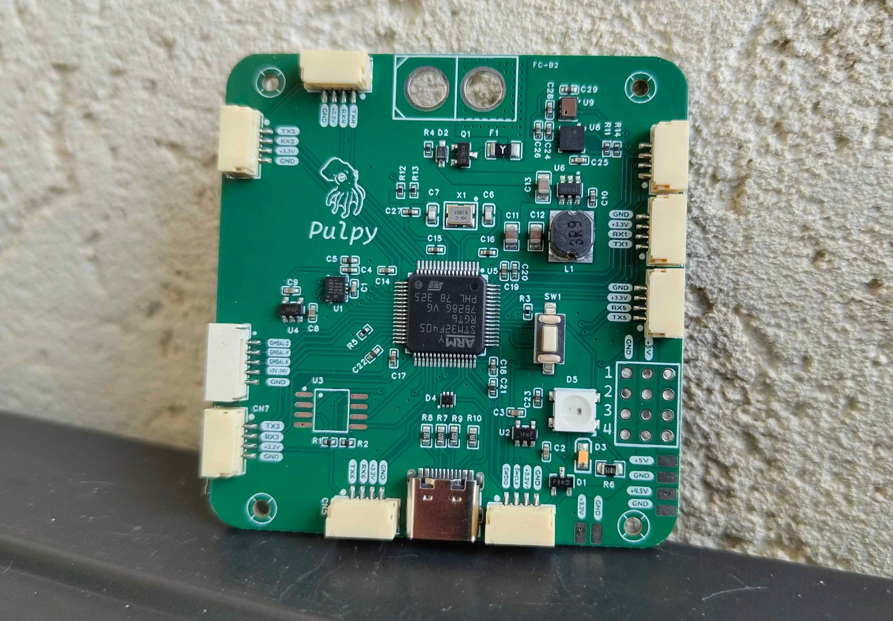
🔹 Second Design
The second design integrates sensors directly, including:
- IST8310 magnetometer 🧭
- DPS368XTSA1 barometer ⛰️
- ICM-42688-P IMU 📡
Other improvements include the addition of a 5V status LED to indicate voltage presence, adjustments in resistor sizing, fine-tuned 5V regulation, and powering the addressable LED at 5V instead of 3.3V for better brightness and compatibility.
📚 Learning Goals
This project is helping me improve my skills in:
- PID tuning & flight dynamics ⚙️
- PCB design for high-speed signals 💻
- Sensor integration and noise filtering 📡
- Firmware configuration with INAV 🔄
📈 Project Status
✅ First prototype tested (except addressable LED)
🔄 Second integrated version in development
⚠️ Due to the soldering complexity of the STM32F405RGT6, I will use JLCPCB’s assembly service for manufacturing.
📹 I’ll soon be sharing a YouTube video on my channel Nayel KHOUATRA to present the design process, testing, and tuning of this project — stay tuned! 🚁
⚡ System Setup
To flash the firmware, you need to download the file inav_9.0.0_PULPYF405.hex, which is only compatible with the latest version of INAV. Once downloaded, open the INAV Configurator, connect your FC to the PC via USB (⚠️ do not plug in the battery at this stage), and use the configurator’s “Load Firmware (Local)” option to upload the HEX file to the board.
When powering the system, follow this sequence to avoid issues:
- Connect the gimbal and ESCs first.
- Plug in the battery.
- Finally, connect the FC to the PC to run your tests.
If you want OSD support, you can use a free UART port to connect an external OSD module. The mounting holes of this FC are designed for M2 screws, making it easy to fit into most standard frames.
🚀 Next Steps
The next generation of this FC will focus on robustness, efficiency, and integration. Planned improvements include:
- Integrated OSD
- SD card slot for blackbox logging
- A more powerful microcontroller
- Dedicated indicator LEDs for BEC status
- A more compact and optimized PCB design
- Power redesign: instead of using two LDOs (one for the IMU and one for the other sensors), the IMU will get its own dedicated LDO while all other peripherals will be powered more efficiently through a buck DC-DC converter for the 3.3V main system rail, avoiding overheating and improving stability
- Additional BECs for external systems, such as powering DJI cameras or other accessories.
Design Drawing
BOM
 Clone
CloneProject Members
 Empty
Empty
Comment