

 Ongoing
Inmp_441Esp32
STDInmp_441Esp32
License
:TAPR Open Hardware License
Description
## Project Overview
This project involves designing a PCB to record sound using the INMP441 microphone with an ESP32 microcontroller. The recorded sounds will be sent to a server for storage and analysis. The PCB includes a J5019 18650 Li-ion battery charger, one push button, and two LED indicators.
### Key Features:
- **Sound Recording:** Using the INMP441 MEMS microphone.
- **Wi-Fi Connectivity:** Using the ESP32 module to send data to a server.
- **Battery Powered:** Integrated J5019 charger for a 18650 Li-ion battery.
- **User Interface:** One push button and two LED indicators.
---
## Components
### Main Components:
1. **ESP32-WROOM-32**: A powerful Wi-Fi and Bluetooth-enabled microcontroller.
2. **INMP441**: A high-performance, low-power, omnidirectional MEMS microphone.
3. **J5019 Charger Module**: A lithium-ion battery charger for 18650 batteries.
4. **18650 Li-ion Battery**: A rechargeable lithium-ion battery.
5. **Push Button**: For user input.
6. **LED Indicators**: For status indication (red and green LEDs).
### Additional Components:
- Capacitors and resistors for power stabilization and signal conditioning.
- Headers for programming and debugging.
- Connectors for the battery and microphone.
---
## Schematics
### Schematic Overview:
The schematic is divided into several parts: power supply, ESP32, microphone interface, user interface, and connectors.
1. **Power Supply Section**:
- **J5019 Module**: Connect the battery to the input terminals of the J5019 module.
- **Battery Connection**: Connect the 18650 battery to the output terminals, providing power to the PCB.
- **Voltage Regulator**: A voltage regulator to provide stable 3.3V to the ESP32.
2. **ESP32 Section**:
- **Power Supply**: Connect the ESP32's VCC to 3.3V.
- **GPIO Connections**: Connect the GPIO pins for the microphone, LEDs, and button.
3. **Microphone Interface**:
- **INMP441**: Connect the VCC to 3.3V, GND to ground, SCK to ESP32 GPIO18, and SD to GPIO19.
4. **User Interface**:
- **Push Button**: Connect one side to GPIO23 and the other to ground.
- **LED Indicators**: Connect the anodes of the LEDs to GPIO21 (red) and GPIO22 (green), with appropriate current-limiting resistors to ground.
### Schematic Diagram:

---
## PCB Layout
### Design Considerations:
- **Component Placement**: Place the ESP32 module centrally for easy access to pins and minimal signal path lengths.
- **Power Traces**: Ensure thick traces for power lines to handle the current without significant voltage drop.
- **Signal Integrity**: Keep signal traces short and minimize crossing over power traces.
- **Ground Plane**: Use a continuous ground plane to reduce noise and improve signal quality.
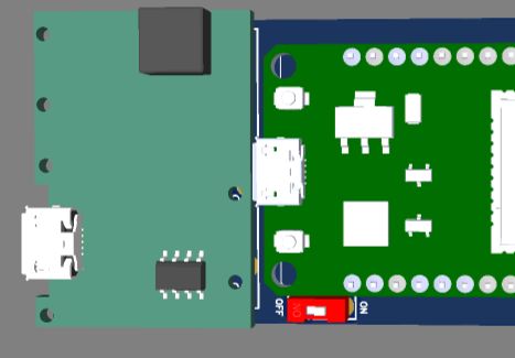
### PCB Layout Image:

---
## Firmware Development
### Development Environment:
- **IDE**: Use Arduino IDE or PlatformIO.
- **Libraries**: Install necessary libraries for Wi-Fi (ESPAsyncWebServer), I2S (ESP32 I2S Library), and HTTP (HTTPClient).
### Code Overview:
1. **Setup**:
- Initialize Wi-Fi, I2S, and GPIOs.
- Configure LEDs and button as input/output.
2. **Loop**:
- Continuously read audio data from INMP441.
- On button press, start recording and send data to the server.
- Use LEDs to indicate recording status and error states.
3. **Data Transmission**:
- Package audio data in HTTP requests.
- Handle server responses and retries.
```cpp
#include <WiFi.h>
#include <HTTPClient.h>
#include <driver/i2s.h>
#define I2S_WS 18
#define I2S_SD 19
#define I2S_SCK 5
#define BUTTON_PIN 23
#define LED_RED_PIN 21
#define LED_GREEN_PIN 22
const char* ssid = "your_SSID";
const char* password = "your_PASSWORD";
const char* serverURL = "http://your_server_address/record";
void setup() {
// Initialize Serial
Serial.begin(115200);
// Initialize WiFi
WiFi.begin(ssid, password);
while (WiFi.status() != WL_CONNECTED) {
delay(500);
Serial.print(".");
}
Serial.println("Connected to WiFi");
// Initialize I2S
i2s_config_t i2s_config = {
.mode = i2s_mode_t(I2S_MODE_MASTER | I2S_MODE_RX),
.sample_rate = 16000,
.bits_per_sample = i2s_bits_per_sample_t(I2S_BITS_PER_SAMPLE_16BIT),
.channel_format = I2S_CHANNEL_FMT_ONLY_RIGHT,
.communication_format = i2s_comm_format_t(I2S_COMM_FORMAT_I2S),
.intr_alloc_flags = ESP_INTR_FLAG_LEVEL1,
.dma_buf_count = 8,
.dma_buf_len = 64
};
i2s_driver_install(I2S_NUM_0, &i2s_config, 0, NULL);
i2s_pin_config_t pin_config = {
.bck_io_num = I2S_SCK,
.ws_io_num = I2S_WS,
.data_out_num = -1,
.data_in_num = I2S_SD
};
i2s_set_pin(I2S_NUM_0, &pin_config);
// Initialize GPIO
pinMode(BUTTON_PIN, INPUT);
pinMode(LED_RED_PIN, OUTPUT);
pinMode(LED_GREEN_PIN, OUTPUT);
}
void loop() {
if (digitalRead(BUTTON_PIN) == LOW) {
digitalWrite(LED_GREEN_PIN, HIGH);
recordAndSendAudio();
digitalWrite(LED_GREEN_PIN, LOW);
}
}
void recordAndSendAudio() {
const int bufferSize = 1024;
int16_t buffer[bufferSize];
size_t bytesRead;
i2s_read(I2S_NUM_0, &buffer, bufferSize, &bytesRead, portMAX_DELAY);
HTTPClient http;
http.begin(serverURL);
http.addHeader("Content-Type", "audio/wav");
int httpResponseCode = http.POST((uint8_t*)buffer, bytesRead);
if (httpResponseCode > 0) {
Serial.printf("Server response: %d\n", httpResponseCode);
} else {
Serial.printf("Error: %s\n", http.errorToString(httpResponseCode).c_str());
}
http.end();
}
```
---
## Server Setup
### Requirements:
- A server with a web server (e.g., Apache, Nginx).
- PHP or Python for handling file uploads.
- Storage for audio files.
### Server Script Example (Python):
```python
from flask import Flask, request
app = Flask(__name__)
@app.route('/record', methods=['POST'])
def record_audio():
if 'file' not in request.files:
return "No file part", 400
file = request.files['file']
if file.filename == '':
return "No selected file", 400
file.save(f"./uploads/{file.filename}")
return "File uploaded successfully", 200
if __name__ == '__main__':
app.run(debug=True, host='0.0.0.0', port=80)
```
### Deployment:
- Upload the script to your server.
- Ensure the server is accessible via the ESP32's network.
---
## Assembly Instructions
### Steps:
1. **Solder Components**:
- Solder ESP32, J5019, and other components onto the PCB.
- Use appropriate soldering techniques for SMD components if applicable.
2. **Mount Battery**:
- Securely mount the 18650 battery and connect to the charger module.
3. **Connect Microphone**:
- Connect the INMP441 module to the designated header.
4. **Install Firmware**:
- Use an FTDI adapter or other programmer to upload the firmware to the ESP32.
5. **Test Connections**:
- Verify all connections and check for shorts or loose connections.
---
## Testing and Troubleshooting
### Initial Testing:
- **Power On**: Ensure the PCB powers up from the battery.
- **Wi-Fi Connection**: Check if the ESP32 connects to Wi-Fi.
- **Button and LED**: Press the button and verify LED response.
### Troubleshooting:
- **No Power**: Check battery voltage and connections.
- **Wi-Fi Issues**: Verify SSID and password, check Wi-Fi signal strength.
- **Audio Issues**: Ensure correct I2S configuration and connections.
Design Drawing
BOM
 Clone
CloneProject Members
 Empty
Empty
Comment