 Ongoing
Nymble Task
STDNymble Task
License
:Description
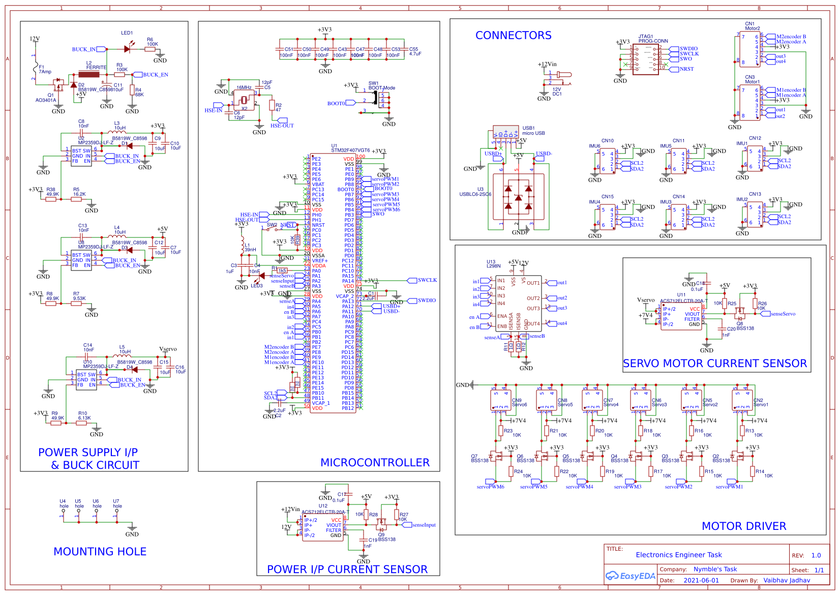
The task requires you to create the Schematic design and the Layout for a PCB to be used for controlling the motion of a DC Servo Motor and a Brushed DC Motor.
The Motor’s shall be controlled by a STM Microcontroller, housed on the same PCB
For designing activity, you can use any software you are comfortable with.
Pre-selected Elements for the design
Geared DC Motor
https://www.pololu.com/product/4869
DC Servo Motor
STM32F407VGT6 MCU
Working Prototype of the system explained below -
Specification
Power
The Board shall be powered by a 12Volt Power supply, with an output current rating of Max 7 Amps
Controller
The Controller on board is supposed to be a STM32F407VGT6, soldered directly on the PCB
Geared DC Motor
This motor shall be used to drive the Stirrer sub-system
We require speed control on the Geared DC Motor, along with Over current protection of 1.75Amps
Should be driven via a suitable Motor Driver (keeping size and cost in context)
Do not use an off the shelf module for this. Make your own circuit
The Encoder input should be channelled to the MCU
DC Servo Motor
This Servo motor shall be used to drive the Dispensing Motion of the lifter shown in the video above
This is a generic Servo Motor, which should be operated at 7.4Volts
We need to provide the servo motor with pre-defined PWM Signals, as detailed in the datasheet
We need to have a reliable input of the Analog output pin of the Motor, to the MCU
The Motor should have a Over current protection of 800mA
Sensors
The PCB should have an input current sensor, providing reliable readings with a factor of 20mA to the MCU, at a max frequency of 50ms
The system requires a precision Accelerometer + Gyroscope connected to the lifter shown in the video above. The readings of this module should be read by the MCU
Safety
The PCB should have intrinsic safety to safeguard against any accidental discharges due to human touch
Connections
All external peripherals need to be connected to the PCB using connectors
Deliverables
Schematic Design of the PCB
Design file in Native format, as well as PDF Format
PCB Layout File for the PCB
Design file in Native format, as well as PDF Format
Schematic and Footprint Library - if made in Altium
Bill of Materials [Excel]
Should include details of all components on the PCB, as well as any external peripherals.
Draft Harness document for this design (assuming a length of 100mm for all external connections) [PDF]
Document explaining the thought process behind major design decisions, including reasoning behind selection of major IC's [PDF]
Bonus Task - In the current design, how would we implement a method of smooth speed controlled movement for the provided Servo Motor? What Hardware or Software modifications would be required to create this functionality?
Design Drawing
 The preview image was not generated, please save it again in the editor.
BOM
 Bom empty
 Clone
CloneProject Members
 Empty
Empty


Comment