

 Ongoing
Flight Controller Design 2.1 - ESCs
STDFlight Controller Design 2.1 - ESCs
License
:TAPR Open Hardware License
Description
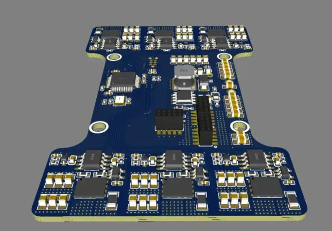
Dual ESC Hardware Overview
This is a compact, dual-channel Electronic Speed Controller (ESC) designed to drive two independent 3-phase brushless motors using a single STM32G431CBT6 microcontroller. Each ESC channel includes its own power stage, current and voltage sensing, and input PWM/DShot control. The design supports both sensorless and sensored BLDC or FOC (Field-Oriented Control) operation.
The ESC is intended to be used in modular, stackable multirotor systems. Two ESC boards can be physically stacked to form a complete quadcopter ESC solution supporting four motors. A shared 12.6 V input power rail is distributed across the modules via 1.27mm header interconnects.
One ESC board provides a regulated 3.3 V output (via onboard LDO or switching regulator), supplying power to an externally mounted flight controller (FC). This eliminates the need for a separate power module. The FC connects directly to the top of the ESC stack and interfaces via standard signal headers for motor control and telemetry communication.
Key features include:
- Dual BLDC motor drive per module, compatible with DShot and PWM protocols
- Stackable design for 4-motor configurations (e.g., quadcopters)
- Shared 12.6 V power distribution between modules via backplane or board-to-board connectors
- Integrated 3.3 V buck converter on one module to power the FC
- Flight controller 1.27mm header interface
Microcontroller Unit (MCU)
- Model: STM32G431CBT6 (STMicroelectronics)
- Core: ARM Cortex-M4 @ 170 MHz with FPU
- System Clock: 16 MHz external crystal oscillator
- Purpose: Central controller for both ESCs; generates PWM, reads sensors, runs FOC or trapezoidal control.
Power Supply (Buck Converter)
- IC: TPS5430DDAR (Texas Instruments)
- Input Voltage (VIN): 12.6 V (designed for 3S)
- Output Voltage (VOUT): 3.3 V
- Purpose: Powers the MCU and logic circuits
MOSFET Power Stage
- FET Model: BSC0924NDI (Infineon)
- Quantity: 6 x 2 N-channel MOSFETs (3 per ESC)
- Configuration: Three half-bridges per motor
- Key Specs:
-
- R_DS(on) ≈ 3.7 mΩ
- V_DS max = 30 V
- Current - Continuous Drain(Id) = 40A
Gate Drivers
- Model: IR2103STRPBF (Infineon)
- Quantity: 6 drivers (3 per motor, each driving one half-bridge)
- Features:
-
- High-side and low-side drive
- Bootstrap operation
Voltage Sensing
- Method: Voltage divider
- Ratio: 10kΩ / (10kΩ + 47kΩ) = ~0.175
- Equation:
-
- V_MCU = V_PHASE × 0.175
- Purpose: Phase voltage monitoring for sensorless control, protection
Current Sensing
- Shunt Resistor: 1 mΩ
- Amplifier: INA180A3IDBVR (Texas Instruments)
-
- Gain: 100 V/V
- Output to MCU:
-
- V_MCU = I_PHASE × 0.1 V/A
- Power Limit: ~1 W → Max current ≈ 30 A
ESC 1 Pin Assignments
| Signal | MCU Pin |
|---|---|
| LED1 | PA12 |
| PWM_IN_1 | PB6 |
| HIN_1A (PWM A) | PA8 |
| HIN_1B (PWM B) | PA9 |
| HIN_1C (PWM C) | PA10 |
| V_SENSE_1A | PB2 |
| V_SENSE_1B | PB12 |
| V_SENSE_1C | PB15 |
| I_SENSE_1A | PB11 |
| I_SENSE_1B | PB14 |
| I_SENSE_1C | PB1 |
ESC 2 Pin Assignments
| Signal | MCU Pin |
|---|---|
| LED2 | PA11 |
| PWM_IN_2 | PB9 |
| HIN_2A (PWM A) | PB10 |
| HIN_2B (PWM B) | PA1 |
| HIN_2C (PWM C) | PA0 |
| V_SENSE_2A | PA6 |
| V_SENSE_2B | PA4 |
| V_SENSE_2C | PA2 |
| I_SENSE_2A | PA7 |
| I_SENSE_2B | PA5 |
| I_SENSE_2C | PA3 |
Programming / Debugging Interface
- Connector: Tag-Connect TC2030
- Interface: SWD (Serial Wire Debug)
Design Drawing
BOM
 Clone
CloneProject Members
 Empty
Empty
Comment