

 Ongoing
LDR Limit Switch Module
STDLDR Limit Switch Module
19
0
0
0
Mode:Full
License
:Public Domain
Creation time:2025-08-05 07:34:07Update time:2025-08-07 09:22:59
Description
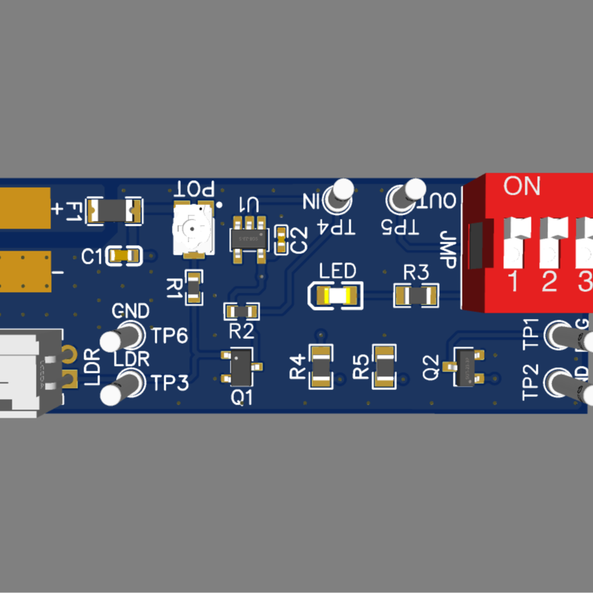
This circuit diagram represents a light-sensitive switch project with the following functionality:
- Power Supply: The circuit is powered by a +5V source, with multiple ground (GND) connections.
- POT (50kΩ Potentiometer): A variable resistor connected to +5V and GND, with its wiper (TP3) acting as a voltage divider to adjust the input signal.
- LDR (Light-Dependent Resistor): Connected to GND and the base of Q1 (S8050 NPN transistor), it detects light levels and influences the circuit's operation.
- Q1 (S8050 NPN Transistor): Acts as a switch, controlling the signal path between the LDR and TP6 based on light input.
- U1 (SNT7LVC1G17DBVR): A Schmitt trigger that stabilizes the signal, connected to +5V, GND, and R2 (12kΩ).
- DSWB08LHGET DIP Switch: This 8-position DIP switch serves three purposes:
- LED Control: One position allows the LED (FC-2012HRK-620D) to turn on when light is detected by the LDR.
- VOUT Test Point: Another position enables a measurable voltage (VOUT) at a test point, which can be monitored with a multimeter.
- Open Drain Logic: A third position provides an open drain output (via Q2) to signal an external microcontroller (MCU) when sufficient light hits the LDR.
- JMP (Jumper): Allows connection or disconnection between the DIP switch and other circuit components.
- R3 (560Ω) and R5 (150kΩ): Limit current to the LED and Q2 transistor.
- Q2 (AO3400A MOSFET): Functions as an open drain connection, enabling logic control (e.g., input to an MCU) to indicate when enough light is detected by the LDR.
- LED (FC-2012HRK-620D): A red LED that lights up based on the DIP switch setting and light input.
- R4 (560Ω): Limits current to the PROG test point.
- TP1-TP6: Test points for signal measurement.
Operation: The circuit functions as a light-sensitive switch. The LDR detects ambient light, and Q1 amplifies this input. The Schmitt trigger (U1) processes the signal, which is then routed via the DIP switch. Depending on the DIP switch settings, the LED can be turned on when light hits the LDR, a VOUT voltage can be measured at a test point, or an open drain output (via Q2) can signal an MCU when sufficient light is detected. The potentiometer (POT) allows fine-tuning of the sensitivity.
Design Drawing
BOM
 Clone
CloneAdd to Album
0
0
Share
Report
Project Members
Followers0|Likes0
Related projects
 Empty
Empty
Comment