

 Ongoing
ESP12-F Grove Sensor Development Board
STDESP12-F Grove Sensor Development Board
License
:Public Domain
Description
Overview
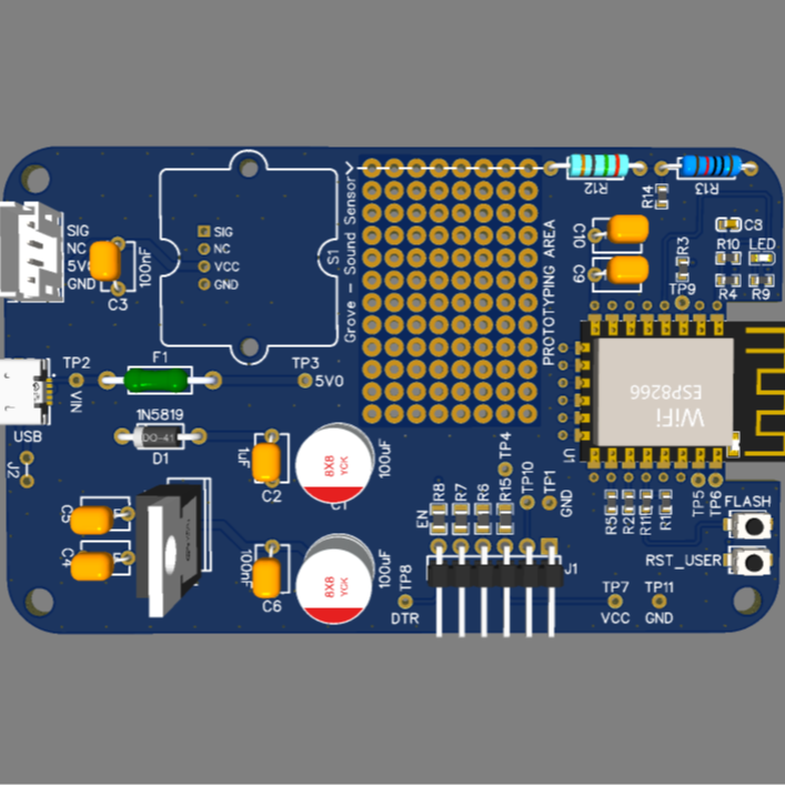
This project is a development board based on the ESP-12F (ESP8266MOD) microcontroller module, designed for use with the Grove - Sound Sensor.
The board accepts a 5 V power input via a Micro USB connector, protected by a fuse and Schottky diode. The voltage is regulated down to 3.3 V using an LD1117V33 LDO regulator, supplying power to the ESP module and peripheral components.
The main purpose of this project is to provide a compact, programmable platform for sound-based applications — such as sound detection, voice-triggered control, or noise level monitoring.
Power Supply and Protection
-
Power Input: Micro USB connector (X1) provides 5 V DC to the board.
-
Fuse (F1): 750 mA polyfuse for overcurrent protection.
-
Diode (D1, 1N5819 Schottky): Prevents reverse current flow and protects the USB source.
-
Voltage Regulator (U2, LD1117V33): Converts 5 V input to a stable 3.3 V output for the ESP-12F and related circuitry.
-
Capacitors (C1–C6): Used for filtering and voltage stabilization (values from 100 nF to 100 µF).
Main Components
1. ESP-12F (ESP8266MOD)
-
Serves as the main microcontroller and Wi-Fi interface.
-
Connected to an external FTDI programming header (J1) for USB-to-UART communication.
-
GPIO pins (e.g., GPIO0, GPIO2, GPIO15) are configured for boot mode selection and normal operation.
-
RESET and FLASH push buttons are provided for programming and system reset.
2. Grove - Sound Sensor
-
Connected via a dedicated 4-pin Grove connector (PH-4A type).
-
Signal output is fed into the ESP’s ADC input through a voltage divider (R12 = 2 kΩ, R13 = 1 kΩ).
-
Allows measurement of sound amplitude as an analog voltage.
Programming and Operation
-
FTDI Header (J1): Enables easy programming and serial communication with the ESP module.
-
Pins: TXO, RXI, DTR, CTS, VCC, GND.
-
The DTR signal is routed to EN and GPIO0 to support automatic bootloader mode for flashing firmware.
-
-
Buttons:
-
FLASH – Forces the ESP into programming mode when held during reset.
-
RESET (RST_USER) – Resets the microcontroller.
-
Technical Specifications
| Category | Description |
|---|---|
| Input Voltage | 5 V DC (from USB) |
| Regulated Voltage | 3.3 V via LD1117V33 |
| Protection | 750 mA fuse + 1N5819 Schottky diode |
| Microcontroller | ESP-12F (ESP8266MOD) |
| Sensor | Grove - Sound Sensor |
| Programming Interface | FTDI header (supports auto-flash via DTR/EN/GPIO0) |
| User Controls | FLASH and RESET push buttons |
| Indicator | Red LED |
| Designer | Markus Virtanen |
| Company | Etteplan Finland Oy |
| Date | October 17, 2025 |
| Revision | 1.0 |
Design Drawing
BOM
 Clone
CloneProject Members
 Empty
Empty
Comment