

 Ongoing
BanFlow
STDBanFlow
License
:Public Domain
Description
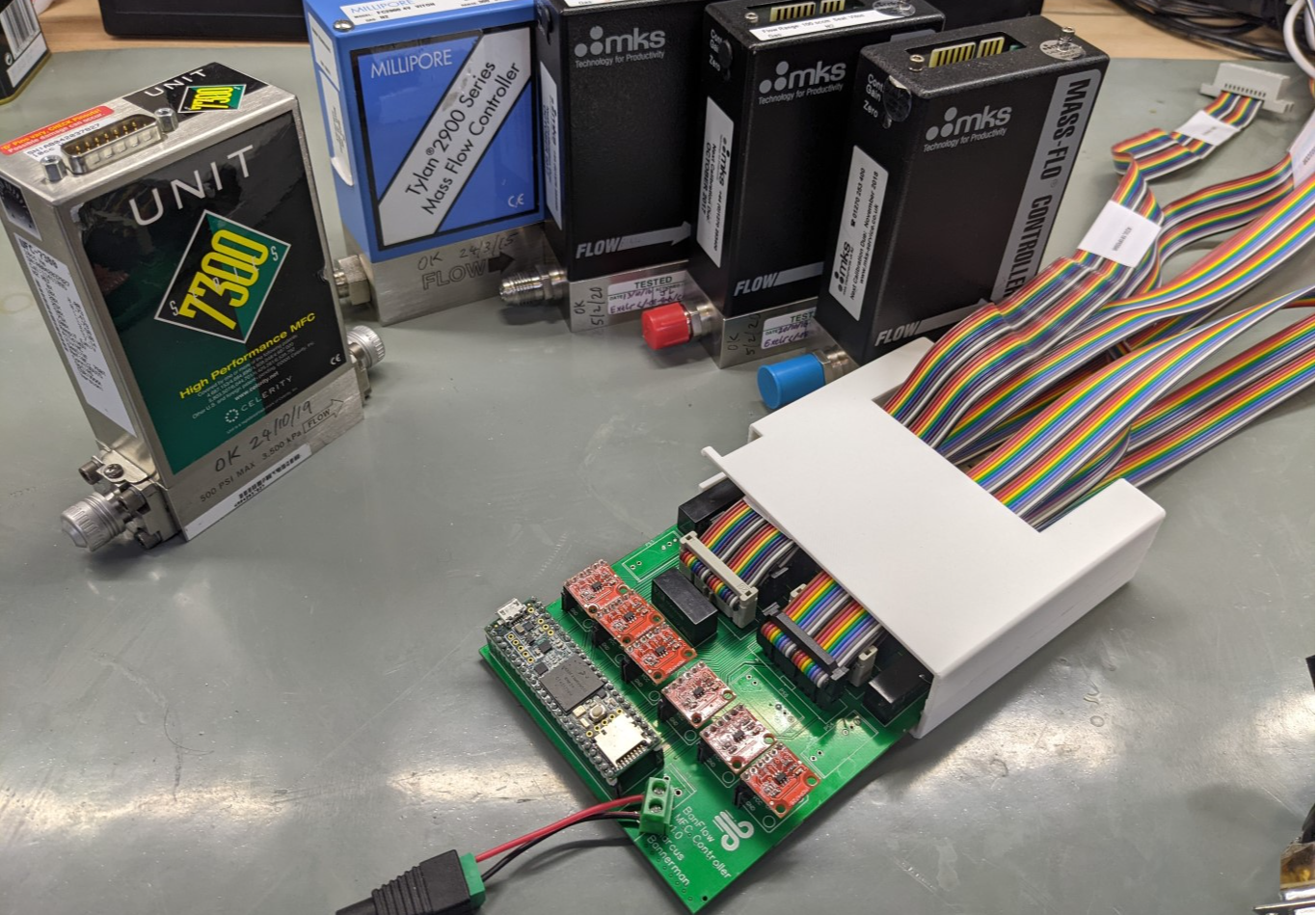
A six Mass Flow Controller PCB for MKS/Tylan card-edge connector style MFCs. The sockets are wired for standard 20-pin IDC cables with a card-edge connector on one end.
The case, and arduino code, are available on github here:
https://github.com/toastedcrumpets/BanFlow
The circuit uses a Teensy 3.6 and its ADCs to read flow voltages and digital IO to command valve open/shut. It also uses six MCP4725 DACs to set the flow across three SPI buses.
NOTE: You must disconnect the pull-ups on the MCP4725's, as they will pull the logic levels to 5V, but the Teensy 3.6 is 3.3V. I have included 3.3V pullups for the I2C buses on the PCB. You must also alternate the A0 pin on the breakout modules as we run two DACs per bus. You will also need to check the bus address of the modules you have. Adafruit have theirs at a different address to Aliexpress!
Current bugs are listed below:
- MAJOR: I've put the SCL3 and SDA3 on the wrong Teensy pins! They should be on digital pins 3&4 not package pins 3&4. This is a simple transpose of two pins, you just need to cut the trace to the current pins and bodge a wire from the correct pins to the pull up resistors instead.
FIXED! - MODERATE: The ITX1215S has an incorrect pinout. There's an additional Not Connected pin on the inside of the input AND output pins. You can still install the modules, just bend the two NC pins flat.
FIXED! - MINOR: The Valve Open line for MFC 4 (VO4) is connected to a analog only pin (A21). We don't really need these pins from what I can tell, its for fully open which is not a useful operating mode for my applications.
FIXED! - IMPROVEMENT: The +-15V power supply is an expensive solution! Needs a cheaper split rail +-15V supply capable of 1.5 Amps (mostly on the positive side). Ideally a switched-mode convertor. Could build something using the MC34063ADR2G but it has a high external BOM count. Seems the best idea though to get a JLCPCB basic parts only solution. Also, from testing loads you only need 3xITX1215S units, and can just bodge wire them up in pairs.
- IMPROVEMENT: The Teensy should use an external 5V reference. We could use a cheap 431 ref, and divide everything into 0-2.5V?
- IMPROVEMENT: Input can be improved. Make sure all inputs (12V and aux 5V) have a on-board break for adding filtering. The 12V at least should have a reverse polarity protection diode on the input, then the input voltage could be set to ~15V? I think the ITX1215S and the LM317 circuit can take that and it gives diode drop headroom.
- IMPROVEMENT: The teensy can do 16 bit PWM analogue output. A cheaper but maybe equivalent design could use the teensy DACs for all channels, just adding a precision buffer jellybean opamp to drive each up to 5V (like the OP07?). This would free up a lot of board space for the switch mode supply too, although the DACs rely on the teensy supplies being stable. Current testing seems to indicate the precision 5V supply is doing a good job of this though.
Design Drawing
BOM
 Clone
CloneProject Members
 Empty
Empty
Comment