

 Ongoing
ROBONOMICS_SLS_GATEWAY_V01
STDROBONOMICS_SLS_GATEWAY_V01
License
:GPL 3.0
Description
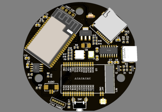
Development kit SLS ZigBee gateway
Ссылка на скачивание прошивок ESP32-WROVER-B и RF-BM-2652P2
https://drive.google.com/drive/folders/1h_XRUVWM8f5BtzlPs-sxU6WpR_D1mZgC?usp=sharing
Для прошивки RF-BM-2652P2 потребуется программа https://www.ti.com/tool/download/FLASH-PROGRAMMER-2
Схема с прошивками полностью проверена и работают.
Для прошивки модуля ESP32 установите на задней части печатной платы переключатели 1 и 3 в положение вкл., остальные выкл.
Для прошивки ZigBee модуля переведите переключатели 2, 4 и 7 в положение вкл., остальные выкл.
После прошивки всех модулей для перевода устройства в рабочий режим установите переключатели 5 и 6 в положение вкл. остальные выкл.
Для дальнейшей настройки зайдите во вкладку Settings->Hardware и пропишите следующие параметры:
Zigbee UART RX: 22
Zigbee UART TX: 23
Zigbee RST Pin: 18
Zigbee BSL Pin: 19
Service Button Pin: 33
PullUp (True)
Led Red (or addr): 21
Led Green: 5
Led Blue: 27
Link to download firmware ESP32-WROVER-B and RF-BM-2652P2
https://drive.google.com/drive/folders/1h_XRUVWM8f5BtzlPs-sxU6WpR_D1mZgC?usp=sharing
To flash RF-BM-2652P2 you will need the program https://www.ti.com/tool/download/FLASH-PROGRAMMER-2
The scheme with firmware is fully tested and working.
To flash the ESP32 module, set switches 1 and 3 on the back of the PCB to on, the rest off.
To flash the ZigBee module, turn switches 2, 4 and 7 to the on position, the rest are off.
After flashing all the modules to put the device into operation, set switches 5 and 6 to the on position. the rest are off.
For further settings, go to the Settings->Hardware tab and enter the following parameters:
Zigbee UART RX: 22
Zigbee UART TX: 23
Zigbee RST Pin: 18
Zigbee BSL Pin: 19
Service Button Pin: 33
PullUp (True)
Led Red (or addr): 21
Led Green: 5
Led Blue: 27
Design Drawing
BOM
 Clone
CloneProject Members
Intellectual Property Statement & Reproduction Instructions
This is an open-source hardware project. All intellectual property rights belong to the creator. The project is shared on the platform for learning, communication, and research only; any commercial use is prohibited. If your intellectual property rights are infringed on EasyEDA, please notify us by submitting relevant materials in accordance with the Rules for Complaints and Appeals of IPR Infringement.
Users must independently verify the circuit design and suitability when replicating this project. All risks and consequences are borne by the user, and the platform assumes no liability.
 Empty
Empty
Comment