

 Ongoing
Controlinator 3000
STDControlinator 3000
License
:Public Domain
Description
Components
Microcontroller: You need one compatible with Arduino Nano. There are few options with different capabilities. Both 30-pin and 34-pin packages are supported. See the next section for more details.
Display: A 2.4” OLED display compatible with the I2C interface. This is the one I used: https://www.aliexpress.us/item/3256805055000425.html
Note: This particular model requires hardware modification to work correctly. Remove the D2 diode and replace it with a straight wire. Without this it won’t send the ACK signal and it will only work in software mode, which is slow. In my experience most similar screens come in SPI mode out of the box and require hardware modifications to convert to I2C. It is possible to redesign the pendant to use SPI, with some modifications to the PCB design and using an extra digital pin
Handwheel: A manual pulse generator like this: https://www.aliexpress.us/item/2251832666651590.html
You need the 5V version to be compatible with the Arduino. The 4-pin version works best. If you have the 6-pin version it will also work, just ignore the bottom two connectors.
I actually ended up using the plastic version from here: https://www.aliexpress.us/item/3256801157578368.html
It is half the weight of the metal wheel (80 grams vs 160), reducing the overall weight of the pendant by 20%
Joystick: I am using a regular Arduino joystick that you can find everywhere. Here’s one example: https://www.aliexpress.us/item/2251832496927403.html
Buttons: You need eight 8mm buttons. They are the smallest ones I could find that still feel like regular buttons. Also one 16mm button for the Self Destruct at the top. It can be red for dramatic effect
https://www.aliexpress.us/item/3256801900884791.html
https://www.aliexpress.us/item/3256804994691187.html
Optional reset switch: You can mount a tiny reset switch that is accessible through a small hole in the front. The existing mount is for this type of switch: https://www.amazon.com/gp/product/B073TYWX86
Microcontrollers
There are few choices that are supported
- A regular Arduino Nano with ATmega 328P. It has 32K ROM and 2K RAM. This is what I used throughout most of the development
- Arduino Nano Every, with ATmega 4809 chip. It has 48K ROM and 6K RAM. The extra memory allows for the display to be mirrored in RAM and to be updated only as needed. This greatly improves the framerate and responsiveness.
I do not own one and haven’t tested it, however I’m pretty confident it would work, since it is very similar to 4808 - An Arduino Every clone with ATmega 4808, like this one: https://www.aliexpress.us/item/3256804681280426.html
It is similar to Arduino Every, however has 4 extra pins, including a UPDI connection that allows programming it without interfering with the USB port. This is what I ended up using in the final version.
Note: While this model has the same general pinout as Arduino Nano, there are subtle differences. The most notable is that the SCL and SDA pins needed to drive the display are on different pins – D4 and D5 instead of A4 and A5 on the Nano. The PCB can be configured to work with one or the other. See below
Other devices may also work if they have the right capabilities and compatible pinout. You may need to edit Config.h to be able to compile the source code.
Few notes on the PCB assembly
- If you have a 30-pin Arduino Nano or Nano Every, use the middle 30 pins. Ignore the 4 corner pins. For 34-pin versions use the entire footprint
- You can solder the Arduino directly to the PCB or use two 17-pin female headers to make it removable. I opted for removable so I can easily experiment during development
- Under the Arduino there are 6 pads that route the SCL and SDA signals for the display. Use two pieces of wire to bridge the middle pads to the left or to the right, depending on your microcontroller. Standard Arduino Nano and Every use the A4 and A5 pins (connect middle and right). The 4808 version uses D4 and D5 (connect middle and left). Check the documentation for your exact device.
I am using a 3x2 right-angle pin header, which allows me to select one or the other with jumpers during development - Optional step: 34-pin versions have an extra programing pin in the top-left. If you want to use it, add a 4.7K resistor to R1 and a 2-pin header to UPDI. Look up “UPDI” online to find tutorials how to use it. If your programming circuit already includes a resistor, replace R1 with a piece of wire
- Optional step: Normally the Arduino would reset if a serial connection is initiated from the PC. This is to allow it to be programmed, however it causes a few seconds delay before it is operational. To avoid that, add a 100nF capacitor to C1 and a 2-pin header to JMP. Then use a jumper on the header to disable the reset. Remove the jumper during programming. If you only use the UPDI for programing, you may short the JMP pads with a piece of wire permanently
- Optional step: RST is for wiring an external reset switch. In my case I have a tiny switch at the front of the pendant, which can be pushed through a small hole with a paperclip
- DISP is for wiring the display. The pins are GND, 5V, 3.3V, SCL, SDA. Use either the 5V or the 3.3V pin depending on the power requirements for your particular model. The display I have worked with either voltage. Only use one of the two – don’t short them together
- Connect a 4x2 right-angle pin header to BTN1..4. This is for the buttons on the left side of the pendant. Right-angle headers allow for a slimmer profile
- Connect a 5x2 right-angle pin header to BTN5..9. This is for the 4 buttons on the right side and for the big Abort button at the top. You can also use a 6x2 header, which exposes pin D11 for expansions
- MPG is for the handwheel
- JOY is for the joystick. The X and Y are marked according to the joystick device, but are reversed in software to account for the mounting orientation
- You can technically solder everything permanently, but I prefer to have cables that are detachable from one end to ease the assembly and disassembly. I have the display and joystick wires soldered to the board with Dupont connector on the other end. The handwheel wires are soldered to the board with spade connectors on the other end. The button wires are soldered to the buttons and connect to the corresponding headers on the board
When assembled, the PCB should look like this:
You can find the 3D printed parts here, both as STL and STP: https://github.com/ivomirb/Controlinator-3000/tree/master/Models
You can use the face plate as is, or print it 1.5mm thinner and add a layer of thin plywood on top. I myself used basswood sprayed with shellac. Use the face_plate.svg file for the shape.
There are 2 versions of the PCB bracket – one for a prototype 40x60mm board and one for the custom PCB from EasyEDA. The hole spacing is different. The bracket assumes that the display connectors are on the right side. You will need to modify the model if your screen has its pins someplace else.
The large parts can be printed at 0.3mm layer height and the small pieces at 0.1. I use PETG for everything. I find it durable and it has a bit of a flex that holds screws well.
Attach the PCB to the top of the bracket using 2mm machine screws and 4 of the spacers. Then screw the screen to the bottom and connect the cable.
The joystick and the screen attach with 2mm wood screws. I used these: https://www.amazon.com/gp/product/B0768H7HTR
The cable clamps and the final assembly of the box use standard 3/4" #4 wood screws.
The reset switch uses 2mm machine screws and threaded inserts that are embedded in the plastic.
You can use different size screws, but you may need to adjust the holes in the 3D models to match.
You will also need a USB cable of some sort. I recommend 6-10 feet long. It needs to match the connector of your microcontroller. It could be micro-USB, mini, or even USB-C.
The cable is held in place by the two halves of the cable holder, connected with M3 screws and 5.5mm square nuts.
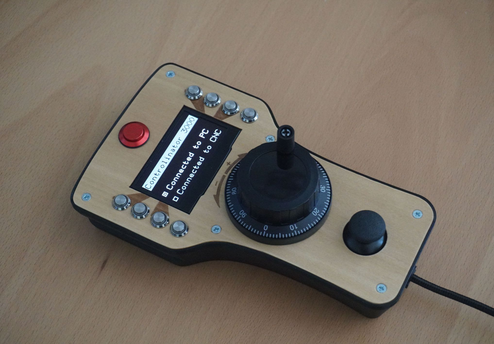
Here’s everything put together:
The software and the 3D models are available on Github: https://github.com/ivomirb/Controlinator-3000
Videos
Design Drawing
BOM
 Clone
CloneProject Members
 Empty
Empty
Comment