

 Ongoing
ShiftStick
STDShiftStick
License
:Public Domain
Description
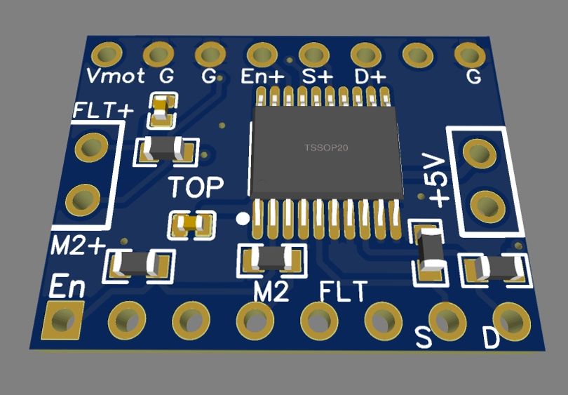
The buffer 74HCT245 converts 3.3V LVTTL to 5V TTL signals with current sufficient to drive optocouplers in typical Industrial/CNC step/dir stepper/servo drivers.
There are two options for providing the +5V needed for operation. You can use a socket header jumper lead to connect +5V from the board this plugs into (if available and capable of supplying ~40mA) to one of the 2-pin header pins labeled +5V on the top. OR Optionally you can solder on the AMS1117-5V (regulator) and two 10uF 35V tantalum capacitors to the back which then uses Vmot (8V to 24V) so the module needs no external +5V source jumpered in.
There is a 2-pin header with an M2 (5V level) output for "digital gearing" or micro-step mode switching and an FLT (fault) input where the normally logic high 3.3V signal (pulled up by a 1k resistor) can be pulled logic low by an stepper driver ALM output.
Instead of attaching a stepper motor directly the same four output pins now carry Ground (-), ENable(+), Step(+), and Dir(+) signals that can be attached to an external stepper or servo motor driver compatible with 5V signaling levels. In this case the wiring is referred to as "common cathode" as the one Ground lead gets attached (only) to each (-) terminal typically labeled EN(-) PUL(-) DIR(-) while the ENable, Step, and Dir leads get attached individually to their respective EN(+) PUL(+) DIR(+) terminals.
Note: the ENable, Step, and M2 inputs from the microcontroller are pulled low by default which typically leaves the STEP/DIR driver enabled for a few seconds while the controller starts up. The Dir and Fault signals are pulled high by default. This arrangement should allow compatability with all OnStep controller hardware including ESP32 based ones.
Design Drawing
BOM
 Clone
CloneProject Members
 Empty
Empty
Comment