

 Completed
Wandering Earth Spherical Steering Wheel
PRO Wandering Earth Spherical Steering Wheel
License
:CC BY-NC 3.0
Description
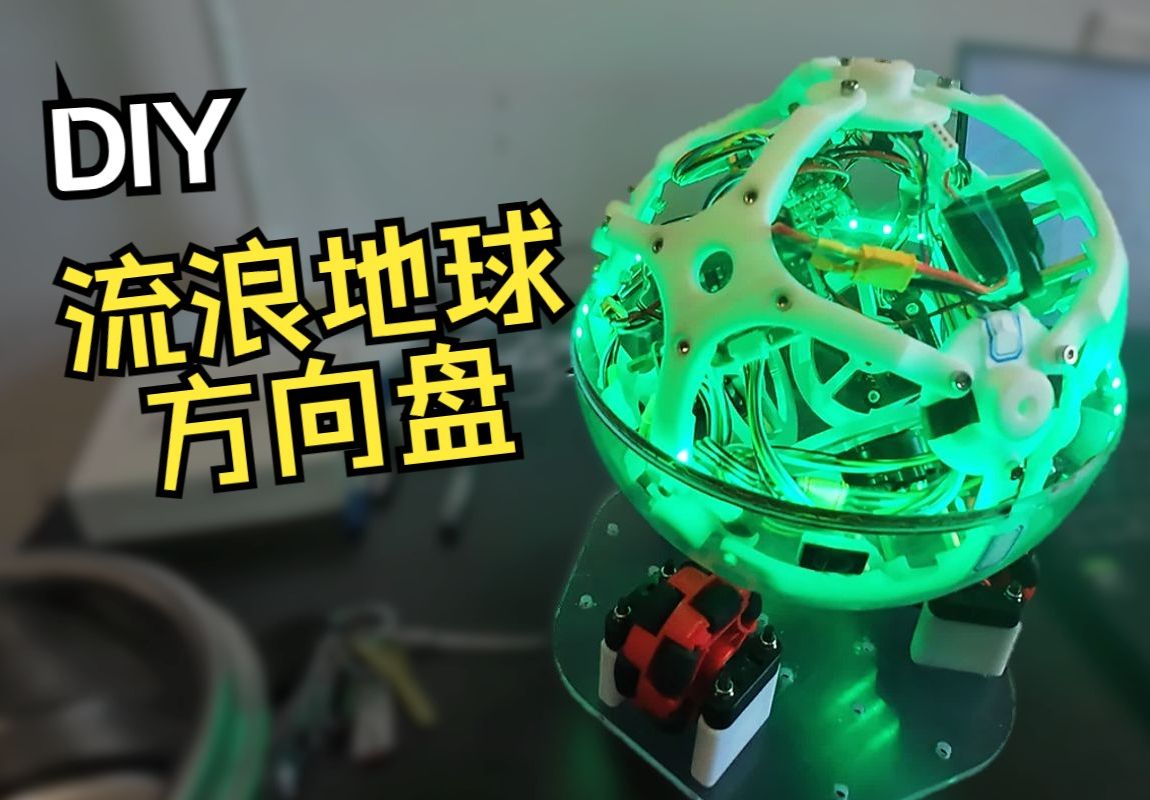
Wandering Earth Spherical Steering Wheel ——by sytnocui 2023/10/18 v1.1
Video link at station b: DIY spherical steering wheel, driving like a wandering earth
0. Sad past events
If you have played in the 2021 e-sports competition, you must know that one of the items in the component list is an acrylic ball. At that time, everyone guessed that the question was a ball robot. For a while, Bilibili was full of videos of ball robots. We also thought about it. I collected a bunch of acrylic balls and spent 200 yuan just to buy them. But perhaps due to postponement of the game due to the epidemic, the final control question was a hospital logistics car that had nothing to do with acrylic balls. While we were breaking through the defense, what to do with the pile of acrylic balls became a problem.
Acrylic balls are slow to sell, please help us! ! !
1. Project description
This project aims to make a spherical version of a balanced cube. In the overall architecture, three brushless motors are used to drive three orthogonally installed flywheels, and the entire ball is placed on a chassis composed of three omnidirectional wheels. Omni-directional wheels allow forward and axial movement, and the chassis composed of three omni-directional wheels allows the balance ball to maneuver freely in all postures with three degrees of freedom. The ball is on an omnidirectional wheel chassis, and the principle of conservation of angular momentum is used to realize the ball's full attitude free maneuver on the chassis. In addition, the balanced cube created by the project can also be connected to a computer and used as a steering wheel to play various racing games. Its operation is similar to the steering wheel in The Wandering Earth.

2. Open source agreement
This project uses CC-BY-NC 3.0. Please indicate the source when reprinting. It cannot be used for commercial purposes.
CC: Creative Commons License
BY: Attribution. You must give appropriate attribution, provide a link to this license, and indicate whether changes were made.
NC: Non-Commercial, you may not use this work for commercial purposes.
3. Project properties
This project is made public for the first time and is my original project. The project has not won any awards in other competitions.
In addition, this project is also a major project for my senior year. It has not yet been completed. Whether it will be passed on to junior students to apply for competitions is still open to discussion.
4. Project-related functions and physical display
- The balance ball rotates freely in all postures
- Balance ball three-axis angular velocity closed-loop control and boost mode
- Balance ball three-axis attitude tracking and follow-up, needs to be completed with a terminal

- The balance ball releases its three-axis posture in real time, can imitate the wandering earth steering wheel, and can be used to play various racing games.

5. Design Principles
The overall project can be divided into three parts: structural design, hardware design, and software design.
5.1 Structural design
The project’s structural design concept draws heavily on Zurich’s classic balanced cube:

According to the picture above, the balanced cube has six sides. According to the distance from the ground, we can divide it into the upper three sides and the lower three sides. It can be clearly seen that the three orthogonal flywheels of the balance cube are installed on the lower three sides, while the batteries, circuit boards, etc. are installed on the upper three sides.
According to the principles of solid geometry, it is logical to think that the cube has an external sphere. Take the outer sphere of the balance cube and project all six faces outward onto its outer sphere, which is our balance ball .
The 3D model established based on this is as follows:
5.2 Hardware design

This project is designed with a main control board, FOC driver board, encoder board and gyroscope board. The project hardware topology diagram is as follows:

Among:
- The main control board and FOC driver board are all powered by cascade, and target instructions are also transmitted through CAN bus cascade.
- There are three FOC driver boards. Each FOC driver board is connected to an encoder board to obtain the position of the brushless motor and drives a brushless motor.
- The main control board is connected to a gyroscope board to read attitude information in real time.
- The main control board is connected to an esp8266 communication module.
5.2.1 Main control board
The main control board is a four-layer board, which can be printed by JLC for free. Mainly completes WIFI wireless communication, reading gyroscope attitude, attitude calculation, control mode management, control algorithm operation, etc.

- Main control: STM32F103C8T6
- Crystal oscillator: Murata ceramic three-legged crystal oscillator CSTCE 8M ( same model as Zhihuijun's robotic arm, no load capacitor is required )
- CAN communication chip: TJA1050T ( note that 5V power supply is required, otherwise the microcontroller CAN transceiver will be stuck )
- Power management: JW5026+ME6211
- Wireless communication: classic pin-type Esp8266 wireless communication module
- All seats used are GH1.25 model;
A treasure can be bought on the estimated cost of a set of about 30rmb (electronic component prices may change).
The supporting encoder boards can be: ICM20602, MPU6050, ICM42688P (there is a temporary problem and serious heating, please use the icm20602 module instead)
Note: The encoder plate is fixed to the innermost vertex of the ball using hot melt glue, parallel to the ground.
5.2.2 Driver board
The driver board is a four-layer board, which can be printed for free by JLC. The driver board mainly completes the FOC rate closed-loop drive.

The driver board design refers to the Lemon FOC open source board and is designed based on GD32.
Reference address: [Happy New Year] Lemon FOC open source board - JLC EDA open source hardware platform (oshwhub.com)
The hardware part of the driver board is designed independently, and the software part directly burns the Lemon FOC code for use. The original open source project can set the current closed-loop, rate and position closed-loop modes through the putty serial port assistant. Due to the needs of the project, the rate step change mode is adopted here.
When using the original firmware, be careful to modify the power undervoltage protection and rate protection parameters in the serial port debugging assistant to prevent the motor from stalling due to too rapid a rate mutation.
The driver board parameters are as follows:
- Main control: GD32C103CBT6
- Crystal oscillator: Murata ceramic tripod crystal oscillator CSTCE 8M
- CAN communication chip: SN65HVD232D
- Power management: JW5026+RT9013-3.3
- Motor driver chip: FD6288T (motor driver chip + mos tube, high current solution)
- NMOS:TPH1R403NL
- Current sampling: LMV358IPWRG4 bias low sampling
- Sampling resistance: 1206 1mR
- All seats used are GH1.25 model
- Supporting encoder: MT6816 ( you need to buy one that supports SPI mode , it is easy to buy the wrong one, don’t buy the wrong one)
You can buy them all on Taobao, and the estimated cost price is around 60rmb for a set (prices of electronic components may vary).
5.2.3BIG Handheld Terminal
The BIG handheld terminal is a two-layer board that can be printed by JLC for free. The BIG handheld terminal mainly completes functions such as remote change of control mode, security management, real-time status display, and release of target poses.

This module is designed based on Zhihuijun's PICO small terminal and mainly completes some human-computer interaction functions. Because it is for beginners, it all looks rough. Because PICO means tiny, Zhihui-kun's PICO is indeed very small, but my handheld terminal is very large, so I named it BIG.
The handheld terminal parameters are as follows:
- Main control: STM32F103C8T6 sapphire core board.
- Display: 7-pin OLED display, SPI mode.
- Battery: 1s lithium battery 300mah.
- Gyroscope: Classic MPU6050 module.
- Wireless communication: classic pin-type Esp8266 wireless communication module.
5.3 Software design
5.3.1 Full attitude resistance effect
It is carried out on the main control board, using the Mahony posture solution method to solve the real-time roll pitch yaw three-axis angle, and establish PID feedback control respectively. Whenever there is an angular velocity on an axis, a control output in the opposite direction is generated on that axis through the PID algorithm. Finally, after superimposing the PID control output of the three axes, multiplied by the rotational speed distribution matrix on the left, it is solved into the rotational speed of three orthogonally installed flywheels, and is output to the FOC drive board, so that the ball can move in the full attitude of the ball with three degrees of freedom. Produce a resistance effect.
5.3.2 Three-axis attitude tracking
On the basis of Section 5.3.1, attitude angle feedback is added, and the BIG handheld terminal collects its own attitude as the target value of the balance ball attitude. The difference with the actual value of the balance ball attitude constitutes a PID controller. Finally, three-axis attitude tracking and follow-up are realized.
Because the omnidirectional wheel chassis will introduce very large friction to the system, this function currently requires the ball to be placed directly on the ground and cannot be placed on the omnidirectional wheel chassis.
Considering that the effect of pure PID is limited, this project will use control algorithms such as LQR to deploy for further comparative testing.
5.3.3 Play racing games as a steering wheel
We accidentally discovered that our ball is very similar to the spherical steering wheel of Wandering Earth, so we used the wifi module to connect to the computer to receive the real-time attitude information of the spherical simulator, and mapped it into the virtual xbox game controller's rocker using python's vgamepad library. Stick values (steering wheel, throttle, brake, etc.). In this way, the virtual game joystick can be recognized in racing games such as Dirt Rally 2.0 and the control data can be obtained.
Because the control data is encapsulated in the form of an Xbox controller, there will be no compatibility issues no matter what racing game you play.

5.4 Concept design (complete work)


Anyway, as long as it is round, you can enjoy the heat.
6. Precautions
6.1 Software description
This project provides the firmware code of the main control board and BIG handheld terminal. The firmware of the driver board is completely consistent with Lemon FOC. Please refer to the Lemon FOC project for burning and use:
Reference link: [Happy New Year] Lemon FOC open source board - JLC EDA open source hardware platform (oshwhub.com)
All microcontroller firmware in this project are developed using Clion. If you are unfamiliar with Clion project configuration, it is recommended to watch Zhihui Jun's Clion+Stm32 environment configuration guide:
Reference link: Configuring CLion for STM32 development [Elegant Embedded Development] - Zhihu (zhihu.com)
6.2 Motor selection
The selection of flywheels and brushless motors is very important. Due to the high friction of the entire system, the low kv gimbal motors commonly used in Lello triangles and balance blocks in the open source community are difficult to meet the torque requirements. I accidentally discovered this motor on Taobao used motors:

After testing, the load capacity of this motor is very suitable for this project, the cost is low (only 16 yuan), and it saves space. Considering that this kind of second-hand motor is often sold out, if the motor is sold out later, you can consider using the DJI 2312 Phantom motor as a replacement.
In addition, if the reaction torque provided by the aluminum alloy flywheel is insufficient, you can imitate the solution of this open source project, make your own flywheel and drill holes on the outer edge to install bolts to increase the rotational inertia of the flywheel.

Reference address: Self-balancing Lello triangle bilibili based on LQR controller
6.3 Gyroscope selection
The gyroscope board involved in this project uses icm42688p. However, different batches of icm42688p purchased from a certain store all showed that although they can read correct data, they have serious heat (about 60 degrees) and serious temperature drift. question. It is confirmed that it is not a welding problem. I don’t know if it is a material problem or a problem with the hardware design. It is recommended to carefully consider purchasing icm42688p from Taobao. This project temporarily uses the icm20602 module of Zhufei Technology as a gyroscope board.
This project currently uses the icm20602 module purchased from the community, and the ball main control board also supports the mpu6050 connector. The driver codes for the three gyroscopes are all in the works, but the interface codes need to be changed by yourself.
7.Project progress
Completed parts of the project:
- The project has completed all structural + hardware design and construction, and the structural and hardware design has matured.
- The project has completed all logic code writing.
- The project has completed the writing of basic control algorithms, and can complete basic angular velocity closed-loop and attitude closed-loop control.
Project follow-up plans:
- Due to the complexity of the control system, the attitude closed-loop control code needs to be optimized later in the project. The main measures include:
- Add counterweight to make the center of gravity approach the center of the sphere and make the inertia of the three axes consistent.
- If PID is really not possible, replace it with a model-based control algorithm, such as LQR modeling based on the Euler equation.
- Identify the parameters of the friction force and use the disturbance observer to compensate it (the ADRC algorithm can also be used)
- Try quaternion-based attitude closed-loop control to eliminate the Euler angle deadlock problem.
- Project members are independently developing FOC driver code based on stm32f103c8t6. After the development is completed, it will replace the currently used driver board based on Lemon FOC's gd32.
- Based on Qt and OpenGL, we will write a PC software that can visualize postures and remotely adjust parameters in real time. For the effect, please refer to Zhihui Jun’s electronic robots and various flight control debugging assistants.
- An embedded shell will be implemented to support remote parameter adjustment through the wifi serial port.
- Add a shock-absorbing pad to the gyroscope to prevent the high-frequency vibration of the motor from causing interference to the gyroscope
- Find out the problem with icm42688p and replace it with icm20602 currently in use
8. Material description
Structural parts bill of materials:
| Supplies | Use | Required quantity | Purchase link |
| Ball main structure | |||
| Acrylic ball shell 20mm | Ball transparent shell | >=2 | https://m.tb.cn/h.54hODsa?tk=Q7ZXdzW9Ydo |
| 3D printing (internal support frame-connected points) | Cross-shaped main frame | 6 | JLC 3D Monkey |
| 3D printing (internal support frame - bridging points) | Main frame connection points | 8 | JLC 3D Monkey |
| 3D printing (bracket-small battery) | Stationary battery | 1 | JLC 3D Monkey |
| Brushless motor related | |||
| Disc brushless motor ZD2808-V1.9 | 3 | https://m.tb.cn/h.5WJTsy4?tk=4qczdC51605 | |
| Aluminum alloy flywheel 6mm 80mm | 3 | https://m.tb.cn/h.5e1xS1N?tk=HlGCdC6gCA1 | |
| Radial magnet 6*2.5 | Get motor shaft position | 3 | https://m.tb.cn/h.54hiYKJ?tk=QM5mdzWTh2m |
| 3M super glue | Attach the magnet to the motor shaft | 1 | https://m.tb.cn/h.54AlcCb?tk=jlEVdzWQEFG |
| Ball body accessories | |||
| M3*8 cup head screws | Main structural fixing screws | Several | |
| M3 lock nut | Main structure fixing nut | Several | |
| Copper pillar M3*10+6 | Main support copper pillar | 20 | |
| M3 5\ 5 embedded nut | Connecting the spherical shell to the 3D printed part | 2 | |
| M3*8 countersunk head screws | Connecting the spherical shell to the 3D printed part | 2 | |
| Counterweight | Center of balance position | Several | https://m.tb.cn/h.56VXPSI?tk=n4DUWYhMTac |
| Circuit part | |||
| Main control board | 1 | JLC provides free board printing and handles the components by itself. | |
| FOC driver board | 3 | JLC provides free board printing and handles the components by itself. | |
| Encoder board | 3 | JLC provides free board printing and handles the components by itself. | |
| Gyro board (optional) | 1 | JLC provides free board printing and handles the components by itself. | |
| BIG handheld terminal | 1 | JLC provides free board printing and handles the components by itself. | |
| Wifi module | Ball and BIG, ball and PC communication | 3 | https://m.tb.cn/h.56vZKps?tk=XmldWYhGjPn |
| The wifi module connects to the computer’s usb serial module | Ball to PC communication | 1 | https://m.tb.cn/h.56vZKps?tk=XmldWYhGjPn |
| Model aircraft battery 3s 550mah 85c | Supply electricity | >=1 | https://m.tb.cn/h.5fuIsF0?tk=Pxn2dzWQvsg |
| Wire | |||
| Silicone wire 18awg | Power cord | Several | |
| Silicone wire 20awg | Motor wire | Several | |
| GH1.25 6p double head reverse 30cm | Encoder line | 3 | |
| GH1.25 6p double head reverse 30cm | Gyro wire | 1 | |
| GH1.25 6p double head reverse 15cm | CAN bus | 4 | |
| xt30头 | Connect the battery | 1 | |
| Chassis | |||
| Acrylic cutting (chassis-upper layer) | Chassis body | 1 | Looking for acrylic cutting on Taobao |
| 3D printing (omnidirectional axle seat-key) | Support omnidirectional wheels | 3 | JLC 3D Monkey |
| 3D printing (omnidirectional axle seat-circle) | Support omnidirectional wheels | 3 | JLC 3D Monkey |
| 3D printing (universal wheel support leg-split type) | Support omnidirectional wheels | 6 | JLC 3D Monkey |
| F car model omnidirectional wheels | Support acrylic sphere shell | 3 | https://m.tb.cn/h.5Vqiebu?tk=y4CAdzW76o4 |
| Bearing 7*11*3 | Connect omnidirectional wheel and optical axis | 6 | https://m.tb.cn/h.54hQEqA?tk=cFWBdzW7L1a |
| Optical axis cutting (omnidirectional wheel optical axis) | Support omnidirectional wheels, pay attention to grooves | 3 | https://m.tb.cn/h.5fuKVfU?tk=G4sGdzW7mtl |
| M4*55 screw | Fixed omnidirectional axle seat | 12 | |
| M4 lock nut | Fixed omnidirectional axle seat | 12 | |
| Foot pads (optional) | Anti-slip base | Several | https://m.tb.cn/h.54AknHL?tk=cSfIdzWjeUe |
The price of the whole set is about 800~1,000 yuan. The prices of some parts vary greatly. Please refer to the actual situation.
Designed by sytnocui (from OSHWHub)
Link:https://oshwhub.com/sytnocui/ping-heng-li-fang-ti-qiu-xing-ba
Design Drawing
 Empty
Empty
Comment