

 Completed
Vision Mini-ESP32S3 Mini player
PRO Vision Mini-ESP32S3 Mini player
License
:GPL 3.0
Description
Let's take a look at a few physical pictures (Happy :))


All open source!!
For projects used in the project, please open the attachment VD_ESP_MINI_Player.zip
For detailed project explanation, move on: Mini - ESP32-based mini player project: Based on the ESP32S3 mini player, this repository contains all the source code projects in the project design for your reference
For all files used by the project, please open the attachment VD_SD_ROOT_FILE.zip (SD card root directory file)
Video explanation, move on:
1. Project background
In a nutshell, the origin of the project.
In the past six months, I have focused on the design of ESP32 audio and video player solutions. At the moment, I have completed the design of several versions, such as:
Video Player Verification Machine: This can be said to be a simplified version of the video player (or verification version)

This version verifies ESP32S3 minimal system, SPILCD driver, SD card, NS4168 audio chip, audio and video player porting....
Large-screen version: Equipped with a 480x272 4.3-inch SPI screen video player, but the video playback effect is not ideal (too stuck)

Shishen 1: This area uses ES8388 as the audio chip, replacing the NS4168 of the previous two generations


PlayerMicro: This generation is actually a smaller version of the Vision1, and it is intended to create a 1.5-inch screen version (but the volume has not been compressed, and the whole machine is a small square box)

Brief reading e-book (open source soon): This generation has replaced the color screen with an ink screen, in fact, the audio base is still the same....

The core of these solutions is based on ESP32S3 chips, and for me, this solution is very mature, and this project will open source a small and simple video player.
2. Project definition
This project aims to design a small and simple video player based on an off-the-shelf ESP32S3 video player project.


3. Project specifications
The project specification is based on the detailed definition of the project, as follows:
3.1 Estimated Specifications
During the project development planning phase, the following project specifications are customized based on preliminary design, concept or by us. Through this general framework, the initial development direction of the product is guided and the feasibility of the product is initially evaluated.
| Content | Device/type | Detailed Specifications: |
| The size of the whole machine | Screen size |
Recommended to use <=2.4-inch LCD screen The following dimensions are for reference (dimensions are width x height) 2.4 inch LCD screen: 42.72 x 60.26 resolution 320x240 2.0 inch LCD screen 34.6x47.8 resolution 320x240 1.8 inch LCD screen 34.00x47.83 resolution 160x128 1.69 inch LCD screen 30.07x37.43 resolution 280x240 1.54 inch LCD screen 31.52x33.72 resolution 240x240 All things considered, the 2.0-inch and 1.69-inch displays were initially selected |
| PCB size |
In principle, the PCB size should not be larger than the screen size (if it is larger, the screen will have black bars, which will affect the appearance) It is required that, in principle, the PCB shall not be greater than the maximum black edge of the screen + the width of the screen, that is, it shall not be greater than the equal width of the four sides of the screen (otherwise it will affect the appearance) |
|
| Component encapsulation |
The components are mainly in 0603 package, and some of the originals use 0805 package |
|
| Processor/MCU | MCU performance requirements |
In principle, the processor should be able to achieve the most basic audio and video decoding capabilities. 1. Audio decoding ability Basic PCM audio decoding capability (software decoding) IIS audio interface (must be hardware IIS, not SPI analog IIS) 2. Video decoding capability Basic MJPEG decoding capability, fast (at least 100ms/image resolution <320x240 image) |
| MCU peripheral device requirements |
In order to control the volume, the MCU peripheral components are required to be as simple as possible and the number of peripheral components is as small as possible |
|
| Power supply | Lithium battery |
Battery type: Uses a polymer lithium battery Battery shape requirements: use prismatic lithium batteries (if you reserve a large space for the audio cabinet, you can use cylindrical batteries, pay attention to control the volume and length) Nominal voltage: 3.7V Charging voltage: 4.2V Charging current: It should not exceed the maximum current that the lithium battery charging chip can provide With Protective Plate: Yes Battery size: Do not exceed the maximum size of the PCB, pay attention to reserve space for the speaker |
| Lithium battery charging |
A charging chip that requires a small number of external components (simple circuitry). |
|
| LDO |
RT9013 Input voltage range: 4.3 - 3.7 Input voltage mode: lithium battery power supply/direct input of charging chip Output voltage: 3.3V |
|
| Power switch | Toggle switch (physical switch) | |
| Display screen | LCD |
Screen connection method: FPC flexible cable connection, directly connected with PCB Screen type: IPS Control chip: ST7789 Number of colors: 65535 colors (sixteen-bit color) Resolution: 320x240 recommended (at least greater than 240x240) Drive: 4Wire-SPI (4-wire SPI ordinary SPI) IO:SPICLK,SPIMOSI,SPICS,LCDWR,LCDCS,LCDRST Backlight mode: LED backlight, support brightness adjustment (not used in this project) Screen size requirements: Refer to the requirements listed for volume control |
| Storage devices | Mass storage devices |
TF Card(microSD) Capacity <32 GB Card type :SDSC SDHC SD card Voltage :3.3V SD card Read mode: File system,FATFS SD card document system: FAT FAT32 supported |
| 音频方案 | IIS audio scheme |
IIS Audio chip communication protocol: IIS Supported audio sample bits: 8, 16 (required), 24
Options: 0. Direct output of single-chip microcomputer The audio signal is output through the DAC or PWM pin of the microcontroller It is required that the microcontroller must have at least high-speed DAC or high-speed PWM (When playing the audio of the 44100, its clock speed must be greater than 44.1KHz) 1. Use the IIS Bluetooth chip to output audio to the Bluetooth headset The microcontroller needs to have Bluetooth and support the Bluetooth audio protocol. Extended IIS Bluetooth module (e.g. BT401)
2. Use IIS amplifier to output audio to speakers Option NS4168
3. Use the IIS audio chip to output audio to headphones Option ES8388 |
| Audio output scheme |
Loudspeaker: Choose 8 ohm speakers Controls the speaker volume
Headphone Socket: Use a 3.5MM headphone socket |
|
| Operational scenarios | Physical button scheme |
Choose from two physical buttons: the dial button and the touch button |
3.2 Detailed Specifications
Detailed specifications refer to the final product specifications after the completion of product development, after detailed design, testing and verification.
| Content | Device/type | Detailed Specifications |
| The size of the whole machine | Screen size |
The screen uses a 2.0-inch screen, and the parameters are as follows: Overall screen dimensions (including bezels): 34.6 x 47.8 mm Screen display range size: 30.6x40.8 mm Maximum black edge size of the screen: 4.2mm (bottom screen driver chip position) |
| PCB size |
In principle, the PCB size should not be larger than the screen size (if it is larger, the screen will have black bars, which will affect the appearance) Ideal PCB size: 34.6x47.8 mm (same as the screen) The maximum size of the PCB is 34.6+4.2 x47.8+4.2mm, which is 38.8x52.0 Note: To reach the maximum size of the PCB is limited to the size of the PCB on four sides + the maximum black edge of the screen, this design can achieve equal width on the four sides. |
|
| Processor/MCU | ESP32S3 |
1. It has the function of audio decoding Support WAV audio decoding, up to 24bit 192K Support software decoding MP3, FLAC and other formats It comes with a hardware IIS interface, which can be connected to output and input devices 2. Have the ability to decode video 3. Simple peripheral devices Developed with the ESP32-WROOM board, only two peripheral capacitors are required |
| Power supply | Lithium battery |
Polymer lithium battery, prismatic Model: 402030 Size:40x20x30mm Nominal voltage: 3.7V Charging voltage: 4.2V Battery capacity: 180mAh Charging Current: 0.05A (50mA) With Protective Plate: Yes |
| Lithium battery charging |
TP4055 charging chip Charging voltage |
|
| LDO |
RT9013 Input voltage range: 4.3 - 3.7 Input voltage mode: lithium battery power supply/TP4055 charging chip input Output voltage: 3.3V |
|
| Power switch | Toggle switch (physical switch) | |
| Display screen | LCD |
Screen specifications used for this project: Screen connection method: FPC flexible cable connection, directly connected with PCB Screen type: IPS Control chip: ST7789 Number of colors: 65535 colors (sixteen-bit color) Resolution: 320x240 Drive: 4Wire-SPI (4-wire SPI ordinary SPI) IO:SPICLK,SPIMOSI,SPICS,LCDWR,LCDCS,LCDRST Backlight mode: LED backlight, support brightness adjustment (not used in this project)
Screen size requirements: The screen uses a 2.0-inch screen, and the parameters are as follows: Overall screen dimensions (including bezels): 34.6 x 47.8 mm Screen display range size: 30.6x40.8 mm Maximum black edge size of the screen: 4.2mm (bottom screen driver chip position) |
| Storage devices | Mass storage devices |
TF card(microSD) Capacity range <32G Supported card type: SDSC SDHC SD card voltage: 3.3V SD card reading mode: file system, FATFS SD card file system: FAT FAT32 is supported |
| Audio schemes | IIS audio scheme |
S4168 audio scheme was selected 1. The peripheral components are simple Only three capacitors + one pull-down resistor are needed for the periphery (to control the speaker off) |
| Audio output scheme |
loudspeaker Choose 8 ohm speakers |
|
| Operational scenarios | Physical button scheme |
Choose from two physical buttons: the dial button and the touch button |
4. Program introduction
4.1 Main Controller
Let's start with the main controller:
The main controller is selected ESP32S3 and uses ESP32-WROOM-S3.
There are three reasons to choose ESP32S3:
1. Develop with a mature solution (I have verified this set of solutions + applied it for half a year)
2. Few peripheral components (only two capacitors are needed, and the rest of the components have been sealed in the device board)
3. The stamp hole is encapsulated for easy welding

Compared with the non-1U board, the WIFI antenna is not onboard, which can effectively save volume.

Reset circuit and Boot button circuit.

Program download: In this project, the ESP32 board is directly connected to the USB, without any burner, and there is no need for the onboard serial port, and the USB can be directly used to burn.
USB download circuit


USB download process:
After confirming that there is no problem with the soldering, open the downloader on the computer where ESP-IDF is installed, I am using VSCode in this case.
Select a device:


After compilation, click to download directly:
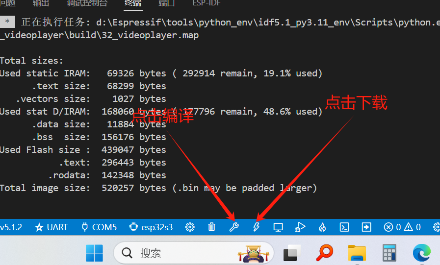
Programming completed:

4.2 Power supply scheme
The energy flow of the power supply is as follows:

Energy Flow Description:
After soldering the lithium battery, turn on 5V, turn off the main power switch, TP4055 will supply power to the lithium battery, the charging LED will light up when charging, and the LED will turn off after charging.

Solder the lithium battery, turn on 5V, turn on the main power switch, and the TP4055 will power the RT9013 and charge the lithium battery at the same time.

Unsoldered lithium battery, turn on 5V, turn on the main power switch, and TP4055 will supply power to RT9013.

Solder the lithium battery, do not turn on 5V, turn on the main power switch, and the lithium battery will supply power to RT9013 at this time.

Note that the main chip can only be downloaded when the USB is connected and the main power switch is turned on (at this time, the USB and power supply are at the same time)
4.2.1 Lithium battery charging scheme
Let's talk about the charging scheme first, the charging scheme uses the TP4055 scheme, and the product characteristics can be seen in the following figure (screenshot of the official document)

In addition to the above characteristics, for our project, this solution has few peripheral components, which effectively saves volume.

A separate switch is used to control the power supply of the lithium battery to the 3.3V LDO, and an LED is used to directly display the charging status.
Debugging instructions
Here is an explanation of the debugging during the soldering process, after the welding of the TP4055 circuit is completed and there is no short circuit and open circuit with a multimeter test, the power supply is turned on and the battery is not soldered, and the switch is not turned on, at this time, the LED is observed to glow slightly, and the voltage should be between 4.2 - 4.3V at both ends of the measurement battery interface (here are two test points).
After the LDO circuit is soldered, after testing with a multimeter without short circuit and breaking circuit, turn on the switch, LED constant, indicating that it is charging (discharging), and measure the voltage at both ends of the LDO, which should be between 3.2 - 3.4V.
4.2.2LDO
The RT9013 is selected here, and a single RT9013 completes the 3.3V power supply of the whole project.

Note: The NS4168 digital power amplifier requires a high current power supply, and the power supply is directly connected to the lithium battery.
4.2.3 Regulator diodes
Two regulator diodes are used in the project to ensure voltage stability:

4.3 Display
Instead of using a display module (which takes up too much space), a bare screen is used instead, which is connected to the PCB via FPC sockets.
The display screen uses a 2.0-inch SPI screen from Zhongjingyuan, and the main control chip is ST7789.
This screen has a good display effect (two-inch 320x240 DPI is OK)

Screen data link (reprint): https://pan.baidu.com/s/13l7iQwqjKUjUb2d99sL2RA Extraction code 8888

4.4 SD Card
Using a MicroSD card, insert the SD card directly into the onboard card holder.

4.5 Audio Scheme
The audio solution uses Nisway's NS4168 amplifier
The scheme is simple, only one IO is needed to control the speaker switch and channel, and three audio cables can automatically play IIS audio when transmitting audio.
Note: The audio chip in this solution uses independent switch control (directly controlling the power supply of the chip), and the hardware level mute can be achieved directly through the power switch of the switch chip.

4.6 Buttons
Here is the main introduction of the dial switch, as follows
Toggle switch:
Here is a note: although the single-chip microcomputer comes with a pull-up resistor, in order to ensure the stability of the key, it is recommended to add a 10K pull-up resistor to the hardware.

Some friends may not look at the connection method of this toggle switch, the following is my learning experience:
The arrow in the middle is the active button, which can be seen from the arrow, and supports left and right toggle and press down.
The 8, 7, 6, and 5 pins are connected in parallel, which can be known as the housing of the dial switch, which is directly connected to the low level, and can also be known by observing the PCB pads.


The 1,2 pins, as can be seen from the figure, are the left and right toggle buttons of the dial wheel switch, and the pull-up resistor needs to be connected to ensure that it is high when it is not pressed.
Judging method: the middle is the active end, the arrow knowledge left dial contact 1, right dial contact 2, you can know that the two switches are left and right toggle switches.

4 is the downward button of the dial wheel switch, which needs to be connected to the pull-up resistor to ensure that it is high when it is not pressed.
Judging method: press the toggle switch down, 3.4 connection, you can know that the switch is pressed.

3 indicates the public end
Note that 3 is connected with the movable lever in the middle, and 3 can be judged to be a common end.
5. Supporting open source engineering documents
Supporting complete project engineering :VD_ESP_Mini_Player.zip
Part of the source code and engineering learn from the self-correcting atom, thank you again to the atomic team!!!!!!!
Please refer to the attachment for the supporting engineering documents of the project, and the following folder will be obtained after decompression, which is the ESP-IDF engineering file.
The project version used is ESP-IDF5.1.2
For a detailed introduction to the open source project, please go to Gitee:Mini - ESP32-based mini-player project: A mini-player based on ESP32S3, this repository contains all the source code projects in the project design for your reference
| Name of the project |
Project description |
| 00_lcd_basic | LCD test program with complete LCD driver and API instructions |
| 01_key_scan |
The key scanning program developed for the dial button and the tap button, the macro definition contains the definition of the identifier of the key press, which will be used in the following project to provide the key press detection and waiting for the key press cycle function. |
| 02_fatfs_test |
Test the SD card and Ftafs file system Prepare test.txt file and place it in the root directory and copy the file to the SD card directory: /System/ |
| 03_chinese_font | Font test |
| 04_wav_player | Simple WAV player |
| 05_mjpeg_videoplayer | Simple MJPEG (AVI) player (the main project file for this project) |
| 06_lvgl_basic | A simple adaptation to LVGL |
All the source projects are uploaded, and they can be opened directly without any activation code or any verification method!!!!!
6. Introduction to the main projects
For a detailed introduction to the open source project, please go to Gitee: Mini - ESP32-based mini-player project: A mini-player based on ESP32S3, this repository contains all the source code projects in the project design for your reference
6.1 wav_player
This project provides a simple WAV audio player, which decodes WAV audio files through software and plays them back by I2S audio devices.
The execution process of the procedure is as follows:
According to the ESP32S3 IIS, we do not need to pass in data regularly, we only need to create a task, and call the IIS write data function in the task in a loop, and directly pass the PCM data in.

This program refers to the punctual atomic music_play project, on this basis, optimizes the key operation, and designs the basic UI of the player.
Music Player Operation:
Compile and burn the program, copy the SD card root directory file to the SD card (directly to the root directory), insert the SD card, and boot the computer.
When executed for the first time, the program will automatically download the font, the font is located in SD:/SYSTEM/FONT, and the program will start to execute after the font is successfully updated.
When the program is playing, it will play the music files in the SD:/MUSIC folder in a loop, and you can control the music player by operating the buttons.
When playing music, the keys are as follows:
Dial Operation: Left and Right Dial: Up/Down Dial Press: Play/Pause
Key Operation: None
Note: If you need to modify the key bits, you can go directly to key.h to modify the key command macro definition. When certain characters are read, the UNI to GBK function may freeze (the state that appears is that the machine automatically restarts).
6.2 video_play
This project provides a simple video player, which decodes AVI (Mjpeg format) video playback through software, and supports video playback with a resolution of 240x180.
Video Format:
| Video format |
AVI |
| Video encoding | MJPEG (must be MJPEG) |
| The size of the video | < 320X180 Recommend 240x180 |
| Video bitrate | < 1000 |
| Video frames per second | < 12 |
| Audio format |
WAV |
| Audio encoding format |
PCM |
| Number of audio bits | 16 |
| Audio sample rate | 11025(<22050) |
| Number of audio channels | 2 |
Using Format Factory Transcoding:


Transcode with Tanuki's Nest Video Converter:

This program refers to the punctual atomic music_play project, on this basis, adapts to the display screen, optimizes the key operation, and designs the basic UI of the player.
The execution process of this procedure:

Simple explanation of the video decoding process:
Videos are stored in the data area as "streams", each stream is followed by data, and the stream header is labeled with the stream information (audio stream or video stream)
When decoding a video, it relies on the clock beat provided by the timer to parse the data of a frame, and the program will determine the type of stream and send it to the audio/video for decoding.

Video player operation
Compile and burn the program, copy the SD card root directory file to the SD card (directly to the root directory), insert the SD card, and boot the computer.
When executed for the first time, the program will automatically download the font, the font is located in SD:/SYSTEM/FONT, and the program will start to execute after the font is successfully updated.
When the program is playing, it will play the video files in the SD:/VIDEO folder in a loop, and the operation buttons can control the music player.
When playing music, the keys are as follows:
Dial Operation: Left and Right Toggle: Fast Forward/Fast Back Press: No Operation
Key Operation: BOOT Button - Next Video
Remark:
If you need to modify the key position, you can go directly to key.h to modify the key command macro definition.
When reading certain characters, the UNI to GBK function may freeze (the state that appears is that the machine automatically restarts)
Please make sure that the video format is correct, if the video format is incorrect, the screen will not be displayed, the video format is wrong, please check the video format!!
Video format errors may be: 1. The video encoding format is incorrect, 2. The video resolution is incorrect (manifested as the display position is incorrect, or the display is overflowing), 3. The video audio encoding format is incorrect.
7. Changelog
If there's a changelog, I'll log it here.
8. Demo video
The demo video is below.
Designed by ZiJinCodeZiJinCode (from OSHWHub)
Link:https://oshwhub.com/zijijncode/esp32miniplayer-shi-pin-bo-fang-qi-v1-3-0
Design Drawing
Intellectual Property Statement & Reproduction Instructions
This is an open-source hardware project. All intellectual property rights belong to the creator. The project is shared on the platform for learning, communication, and research only; any commercial use is prohibited. If your intellectual property rights are infringed on EasyEDA, please notify us by submitting relevant materials in accordance with the Rules for Complaints and Appeals of IPR Infringement.
Users must independently verify the circuit design and suitability when replicating this project. All risks and consequences are borne by the user, and the platform assumes no liability.
 Empty
Empty
Comment