

 Completed
[Verified] IP5389+BM3451 small volume mobile power supply
PRO [Verified] IP5389+BM3451 small volume mobile power supply
License
:CC BY-NC-SA 3.0
Description
Please refer to the attached content for the BOM list! Errors may occur when the system is automatically generated!
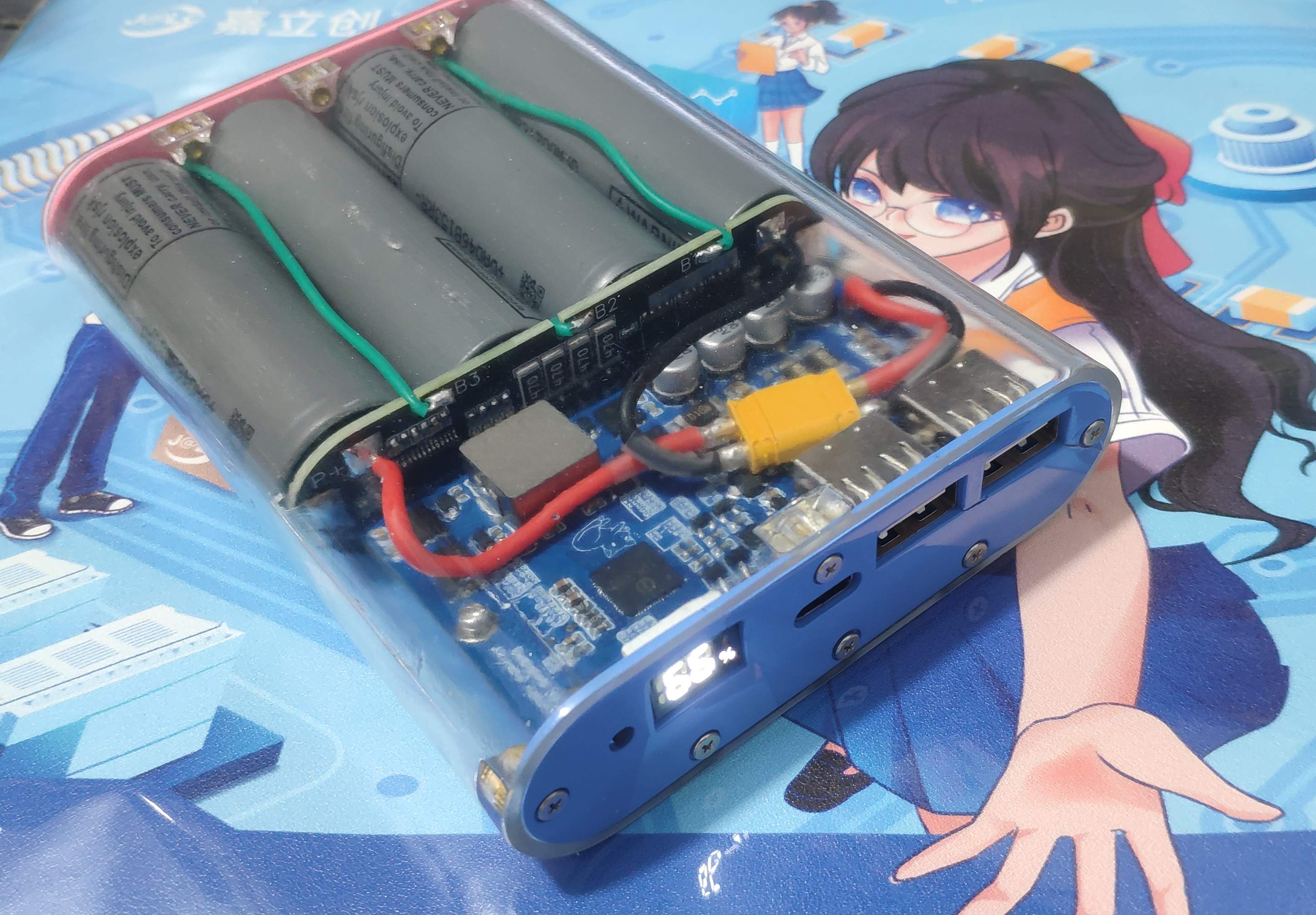
A 100W bidirectional fast-charging mobile power bank based on Yingjixin's IP5389-BZ main control and BYD BM3451TNDC_T28A protection chip.
The motherboard and protection board are modified from Xiao Yu's brother's version, and I would like to thank the big guy for open source
https://oshwhub.com/wzw666/IP5389PRO
https://oshwhub.com/wzw666/bm3451
==============MASTER WARNING==============
This project may include the following:
High-current baking plate, pin tin connection, VCC short circuit, power supply recharge, copper skin shedding, I2C docking UART
If you feel unwell, please adapt as soon as possible.
=========================================
Materials used:
188 Digital Tube Link (Click to Jump)
M2*3.5*4 copper insert nut link (click to jump)
M2*5 Flat Head Screw Link (Click to jump)
M2*8 Screw & Nut Set (For Locking Motherboard)
Main control board part:
Except for the main control pitch of 0.4, which needs to be noted, all other welding methods are standard.
The main control is welded first, then the resistor is welded, the sampling resistor is then loaded, and finally the digital tube, the tact switch, and four electrolytic capacitors. Except for the Type-C seat, don't go to the A exit first.
Plug in the battery, the digital tube shows 0%, at this time ignore it. Multimeter voltage range. The black pen is grounded, the red pen measures TP8, there should be a voltage of 11.2~16.8V, if it exceeds this range, please check the protection board or battery.
Then insert the C port of the charger into the C port of the motherboard, at this time, the digital tube will display the current battery level, measure the TP2, whether there is a voltage of 4.8V and above, if there is no check for the welding problem of the C port of the motherboard.
After the previous step is completed, measure whether the voltage of TP8 is consistent with TP2, and if not, check whether there is a problem with the H-bridge welding and the master control welding.
After the above steps are all right, go to port A, connect the cable and measure the voltage of TP3 and TP4 ports accordingly. It can also be output from the C port to measure the TP2 voltage (when the two ports and above are output at the same time, the TP1 voltage will only have 5V, and the single port can trigger 5V, 8V, 12V, and 20V voltages, but the 20V voltage is limited to the output of the C port alone, and the maximum voltage of the A port alone can only reach 12V).
At this point, the motherboard soldering is complete.
Lithium battery protection board part:
Protection board specifications: 4 strings, protection current 20A, long-term use within 15A.
BM3451 is welded first, then resistor-capacitance, dissipation resistance, equalization MOS and sampling resistance are welded, and finally 4C302 is welded.
Note:
As much tin as possible is piled up in the windowed part of the MOS tube to ensure that the plate will not be burned when the current is high.
The LED can be back-blown by the method, and the LED lens will not be hot and yellowish if the tin paste is applied at medium temperature.
The welding sequence of the protection board is B-, B1, B2, B3, B+, otherwise there is a probability of all kinds of strange problems (such as the output voltage is only 8V)
In terms of battery, I use LG M50LT myself, and other battery cells have not been tested.
====================================
And then it's just a random drawing.Gray is often simple~.

Open the hole, do a good job of countersunk design.

Wow, the insert nut is opened, isn't it very simple.
wait for a few days in Lichuang 3D printing, and install it when you go home, and take a mouse pad by the way.


When Lichuang 3D placed an order, the shell was selected 8001 resin, and the post-processing was about to catch up with the shell material cost itself.
The nut of the upper copper insert should not be squeezed violently or baked at high temperature, as there is a probability that it will be broken.
The correct method is to polish the mounting hole with a 3mm drill bit before loading the piece, which can be opened to 3.3mm, and then put the nut on the pointed soldering iron and heat it for 5~8 seconds, remove it with tweezers, slowly press into the mounting hole, and use the 502 dispensing dropper to drop a little bit into the nut gap after the installation is in place, and you can see that the glue is infiltrated not too much.
==================E N D===================
Designed by voidloop (from OSHWHub)
Design Drawing
 Empty
Empty
Comment