

 Completed
TYPE-C to HDMI+USB3.1+PD
PRO TYPE-C to HDMI+USB3.1+PD
License
:GPL 3.0
Description
0.There is a new version that uses TYPE-C female socket with MUX chip reversible plugging, and it is recommended to make a new version.
https://oshwhub.com/aknice/dai-mux-de-type-c-zhuan-hdmi-usb3-1-pd
Erratum
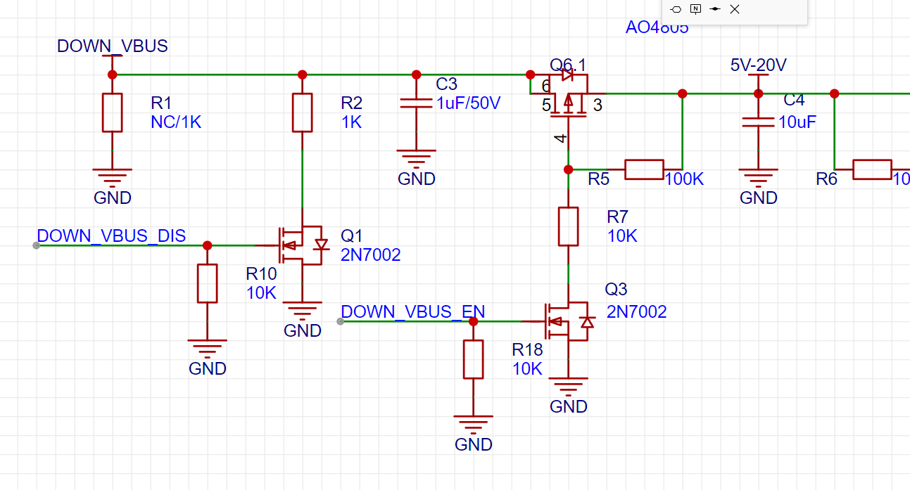
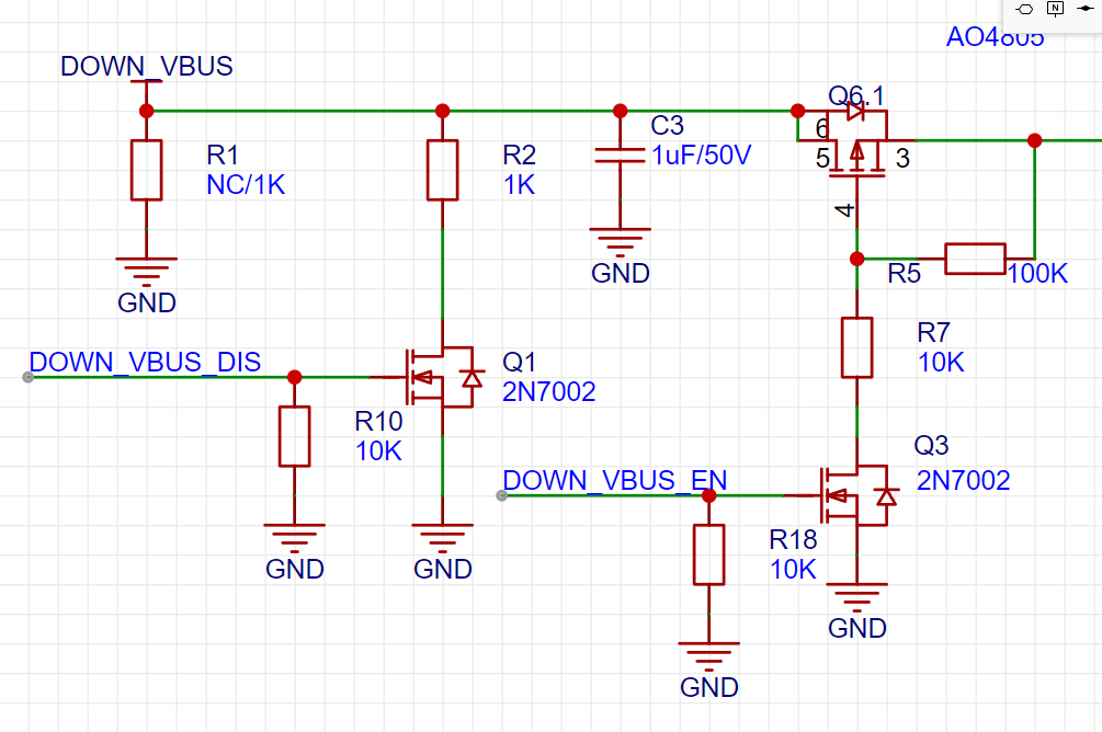
Today, it is found that Q1 and Q5 MOS pipes are connected incorrectly (as shown in the figure above), and the correct connection method is as shown in the figure below. This connection error does not affect the normal use, this MOS is only used for discharging when unplugging, and has been corrected. Thanks to @雷老师讲电子 errata.
1. Introduction
CS5266 is a USB TYPE-C to HDMI1.4b 4K-30Hz controller with PD3.0 and USB3.1.
Compatible with Nintendo SWITCH, most Win laptops.


2. TYPE-C DP knowledge supplement
Regarding TYPE-C heads, most of the TYPE-C docking stations with video output that are actually sold on the market are either directly plugged into male heads like mine.

Either it has a small tail, and it is called a urine bag design.


And the latter is the majority.
Why is their design so stupid, why not make a female TYPE-C docking station, and then connect it with a male-to-male cable, so that the line machine is separated, which is not only easy to store but also beautiful.
In fact, there are such split docking stations, but they are very expensive.

This is actually related to the characteristics of TYPE-C. The following is the personal opinion and personal information collected if there are any errors welcome to point out. First of all, we know what the full function of 24P TYPE-C each signal foot does.
2.1 Functions of individual lines [1].


In USB3.2 Gen1 and Gen2, TYPE-C uses a set of two differential pairs of four wires to achieve 5Gbps and 10Gbps transmit and receive signals, i.e., SSTX differential pair and SSRX differential pair, respectively.
There is also a set of differential transmission signals for USB2.
2.2 Transfer Video for TYPE-C [2]
First of all, please pay attention to distinguish between DP (DisplayPort) and PD (USBPowerDelivery)
The USB PD is transmitted on the CC (Configuration Channel) pin, and the PD has a VDM (Vendor defined message) function, which defines the device ID, and reads the device that supports DP or PCIe, and the DFP enters the alternate mode.
If the DFP recognizes the device as DP, switch the MUX/Configuration Switch to let the Type-C USB3.1 pin transmit the DP signal instead. AUX assist is transmitted by Type-C SBU1 and SUB2. HPD is a detection pin, which is similar to CC, so it is shared.
A complete DP interface also contains 4 pairs of main connection differential pairs, Mian Link Lane 0~3.
DP can also work in the mode of only ML0 and ML1 two lanes

For TYPE-C DP transmission, there are three modes.
(1)DP Alt Mode 4Lane
DP has lane0-3 four groups of differential signals, Type-C has RX/TX1-2 is also four groups of differential signals, so it is no problem to completely replace them.


(2)DP Alt Mode 2Lane
The alternative mode in the DP protocol can transmit USB signals and DP signals at the same time, RX/TX1 transmits USB data, RX/TX2 is replaced by lane0, 1 two sets of data transmission, and can support up to 4k at this time.


(3)Virtual Link
Virtual Link, which sets the USB 2.0 pins to USB3.2 Gen1 or Gen2, was developed for VR applications, and is supported by Type-C on Nvidia's 2000 series and AMD's 6000 series graphics cards.

Most of the general use is the 2Lane mode, which is also the mode of our CS5266 chip.
2.3Alt Mode requires a multiplexer[3][4].
(This document is from TI)
Based on the requirements of a specific Alt Mode standard, a single Type-C interface can reside one or more protocols.
For example, the Video Electronics Standards Association (VESA) DisplayPort's Alt Mode on the Type-C standard can establish a 4-channel DisplayPort, or it can create USB3.1 and DisplayPort simultaneously. With multiprotocol support and reversible Type-C, multiplexing between different protocols is necessary to connect data and video sources to appropriate terminals.
On the source side, a multiplexer (MUX) switches the USB and DP channels to a suitable high-speed channel. On the receiver side, the multiplexer takes 4 high-speed channels from Type-C as inputs, and then distributes the signals to the USB receiver or DP receiver accordingly. Figure 4 (below) shows the source-receiver signal path for advanced Alt Mode communication, as well as where the multiplexer is placed.

DisplayPort is the most popular type of Alt Mode today, and it also supports high-resolution video output. In order to meet the different applications and the reversible characteristics of Type-C, these 4 different signal configuration scenarios require multiplexer support:


In this document, it is mentioned that a Type-C Alt Mode switcher can be used for channel equalization and signal output quality if it has a built-in linear repeater (Mux). The repeater is directional, it can only relay the signal in a specific direction, so it should be equipped with a Type-C Alt Mode repeater/switcher at the signal transceiver/receiver end. Figure 7 (above) illustrates an example of a transceiver use case.
So to sum it up: in fact, when doing USB-C DP, you should need a repeater (Mux), which can do signal compensation, and most importantly, can do signal crossing.
But in fact, most docking stations with a small tail or a direct male head with video output only have a PD controller and no MUX.
This is because this Type-C definition is directly soldered rather than plugged into a Type-C port at will, so there is no need for MUX to deal with Type-C reversible insertion in the design, which is also mentioned in Cypress's guidance [5].
If you are using type-C receptacle and plug combination you will not need a switch. If you have both USB-C connectors as receptacles, connected via a type-C cable (EMCA) then you will require a switch.DP source (FPGA) <---->Switch<------> USB-C receptacle <---------------------> USB-C plug <------> DP sink (FPGA)otherwise,DP source (FPGA) <-----> Switch <-----> USB-C receptacle <---------- USB-C cable ----------> USB-C receptacle <-----> Switch <-----> DP sink (FPGA)
Therefore, the summary is that using a small tail or directly connecting to the PD controller in the form of a male connector can save a MUX chip.
In addition, the MUX chip is for DP transmission, and USB transmission is recommended to also need to flip the chip, such as the very commonly used VL160.
See this article for details: https://blog.csdn.net/ai126323/article/details/120333537
The flip of TYPE-C cable is explained in detail.

For MUX's project, you can take a look at this bigwig's project.
https://oshwhub.com/lemon_wifi/CH543

References:
[1]^USB-PD3.0(Power Delivery) charging protocol https://blog.csdn.net/ai126323/article/details/120333537
[2]^Type C & DP Introduction https://blog.csdn.net/u010538116/article/details/122776717
[3]^USB Type-C's Alternative Mode: Beyond USB https://zhuanlan.zhihu.com/p/335164290
[4]^Type-C Extender Solution Guide (DP Alternative Mode) https://zhuanlan.zhihu.com/p/342165494/#ref_8
[5]^Cypress Ask whether MUX is needed on the device side https://community.cypress.com/t5/USB-EZ-PD-Type-C/do-we-need-a-switch-like-PS8740B-on-both-the-source-and-sink/td-p/187782?start=0&tstart=0
3. Actual measurement
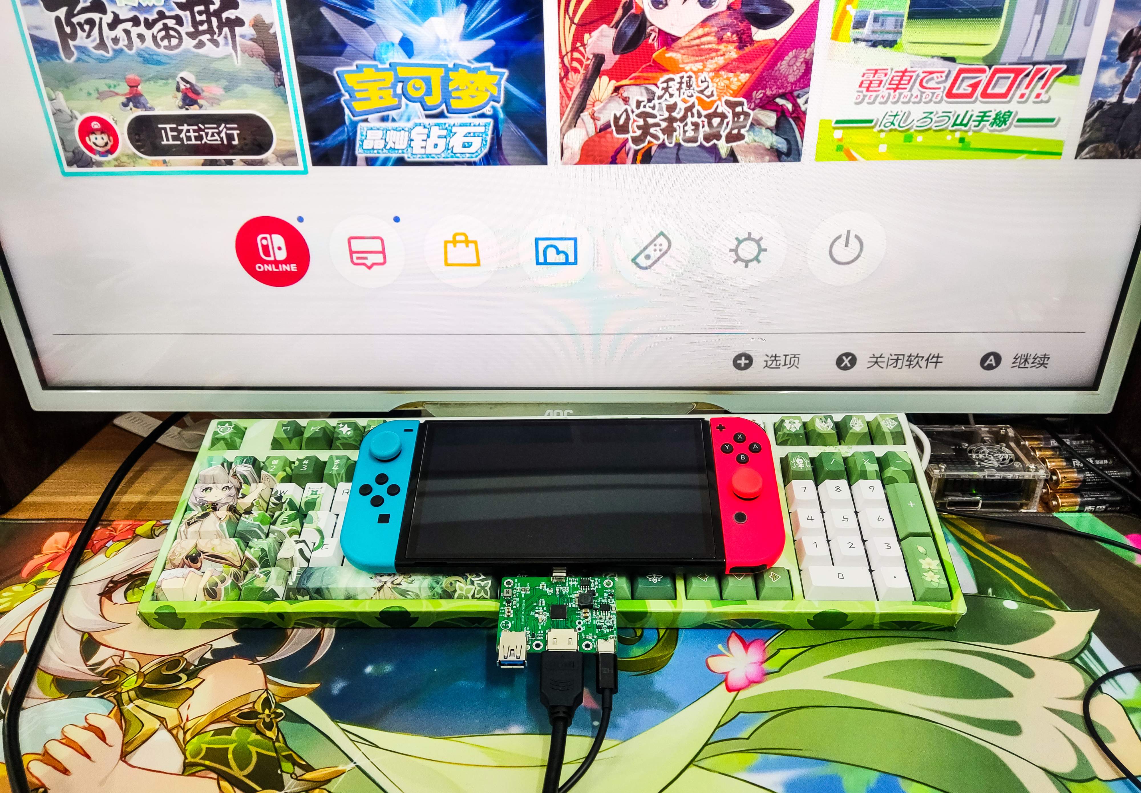
Compatible with Nintendo SWITCH (OLED version) 15V fast charge +HDMI output.

Most Windows notebooks.
20V fast charging + HDMI output + USB3 transmission.


Measured USB3 transmission, the hard disk limit is not too high.

About CC pin PD and DP communication.

Charger CC provides a choice of charging specifications.

The PD controller selects the power supply specification.

VDM, enter alternate mode.

Determine the DP.

This is consistent with the DP communication process supplemented in 2 above.
4. LAYOUT SECTION
With a thickness of 1.0, a four-layer board, and an impedance structure of JLC04101H-7628.
HDMI, DP part goes 100 ohm impedance matching.
The signals of TYPE-C B2, B3, A10, and A11, and HDMI D0, D1, D2, and CLK need to go

The USB section goes 90 ohm impedance matching.
TYPE-C's A2, A3, A6, A7, B10, B11 singnals need to go.

5. Chip purchase
According to other friends, the CS5266 chip he purchased does not recognize NS, only WIN notebook.
As far as I know, there is also a MAC notebook firmware of CS5266 and a firmware with MUX chip control, and the devices that may be compatible with different agents are different.
I purchased the chip here, and I can place an order directly.
https://item.taobao.com/item.htm?spm=a1z09.2.0.0.6d9b2e8dJXyE26&id=652192213048&_u=7qavhl896d3

6. Measured video
Designed by __Aknice (from OSHWHub)
Design Drawing
 Empty
Empty
Comment