

 Completed
Two-axis satellite tracking head based on Arduino and ESP32-C3
PRO Two-axis satellite tracking head based on Arduino and ESP32-C3
License
:CC BY-SA 4.0
Description
Project Description
The main control uses a combination of Arduino and ESP32-C3. ESP32-C3 connects to the IMU (BMI270, BMM150) through I2C to obtain nine-axis data, calculates the current pitch angle and azimuth angle of the gimbal, and feeds it back to Arduino through the virtual Soft serial port. Arduino communicates with the computer through the USB serial port. Host computer communication compares the current position of the pan/tilt to control motor operation.
Open Source Agreement
Adopt CC-BY-SA 4.0 open source license.
Project Related Functions
Arduino is responsible for communicating with the computer host computer and controlling the rotation of the gimbal motor through PWM. The ESP32-C3 and the IMU module obtain the current position information of the gimbal through I2C communication. The power supply uses the XT30 interface 12V independent power supply. The top rocker can be used to manually control the gimbal. Pitch, Arduino calculates and controls the motor's rotation direction and rotation speed based on the XY axis position of the joystick.
Project Properties
This project is made public for the first time and is my original project. The project has not won any awards in other competitions.
Project Progress
2023-09-22
1.The second load test of the gimbal is completed. The actual measurement shows that the center of gravity is balanced and the assembly is correct. It can be used. Heavy antennas may have insufficient pitch motor torque and require hand support to lift. The overall design is completed and the first phase of the project is completed.
2.The IMU part is waiting to be redesigned after the stepper motor may be replaced in the second phase of the project.
2023-09-12
1.The gimbal's conductive slip ring plate has certain size issues, but it is still usable for comparison and will be modified later based on the size.
2.When installing the conductive slip ring, the length of the fixing screws was insufficient. Extra lengthened fastening screws were purchased.
2023-08-28
1.The gimbal failed the load test, and the stress point connecting the acrylic and flange at the bottom cracked. It is planned to add 2-3 fastening plates to make the gimbal and the light stand tight.
2.The motor torque is insufficient. Plan to replace the DC motor with a stepper reduction motor.
2023-08-21
1.The overall hardware assembly is roughly completed. The hole position deviation of the pitch axis arm linker rod assembly plate is 90° and has been updated in the engineering file.
2.The Panel file has been updated and new hole positions have been added to support the installation of 42 stepper motor deceleration and DC motor deceleration solutions. In the future, we may consider switching to DC motors with rotating magnetic encoders or 42 stepper motors.
3.Added IMU panel and JY901S module project files. Consider replacing the IMU with JY901S in the future.
2023-08-19
1.The hardware is complete, but there are assembly conflicts during assembly (1. The horizontal axis motor conflicts with the mounting copper column; 2. The screws are skewed after passing through the nut, causing the assembly to not be in place). The panel file has been modified to expand the hole position by 0.3mm, and the motor assembly position is adjusted and rotated. Fix the copper pillars at a staggered angle of 45 degrees
2.IMU part Yaw-Module, I2C cannot communicate after IMU-Module is welded, and the follow-up plan is to re-solder the two sensor boards.
2023-08-17
1.It is expected to add an IMU transfer board, move the BMM150 from the IMU-Module to the transfer board and install it on the horizontal rotation axis as a horizontal electronic compass. At the same time, the board will lead the XH2.54 4P interface line sequence from the control board where the esp32 is located. Turn to the normal direction and retain the BMM150 on the original IMU-Module board for possible subsequent updates to the IMU attitude fusion calculation algorithm.
2.The panel with the wrong part of the assembly hole has been re-ordered and prototyped. The hardware has been ordered and is expected to arrive around the 21st. IMU has added a transfer station. Yaw-Module PCB has been ordered and prototyped.
2023-08-15
1.The circuit part is roughly completed. The structural part uses a 2.8mm thick acrylic panel printed by JLC Panel. The hardware for panel assembly has not yet been purchased. The assembly hole size of the panel part is wrong and needs to be re-sampled.
Design Principles
1.The pitch axis elevation angle is calculated based on Kalman filtering and the roll angle and pitch angle from the accelerometer and gyroscope data. The Roll angle is selected as the pitch angle data based on the position of the chip on the PCB.
2.The horizontal direction angle is obtained by the BMM150 installed on the horizontal rotation axis.
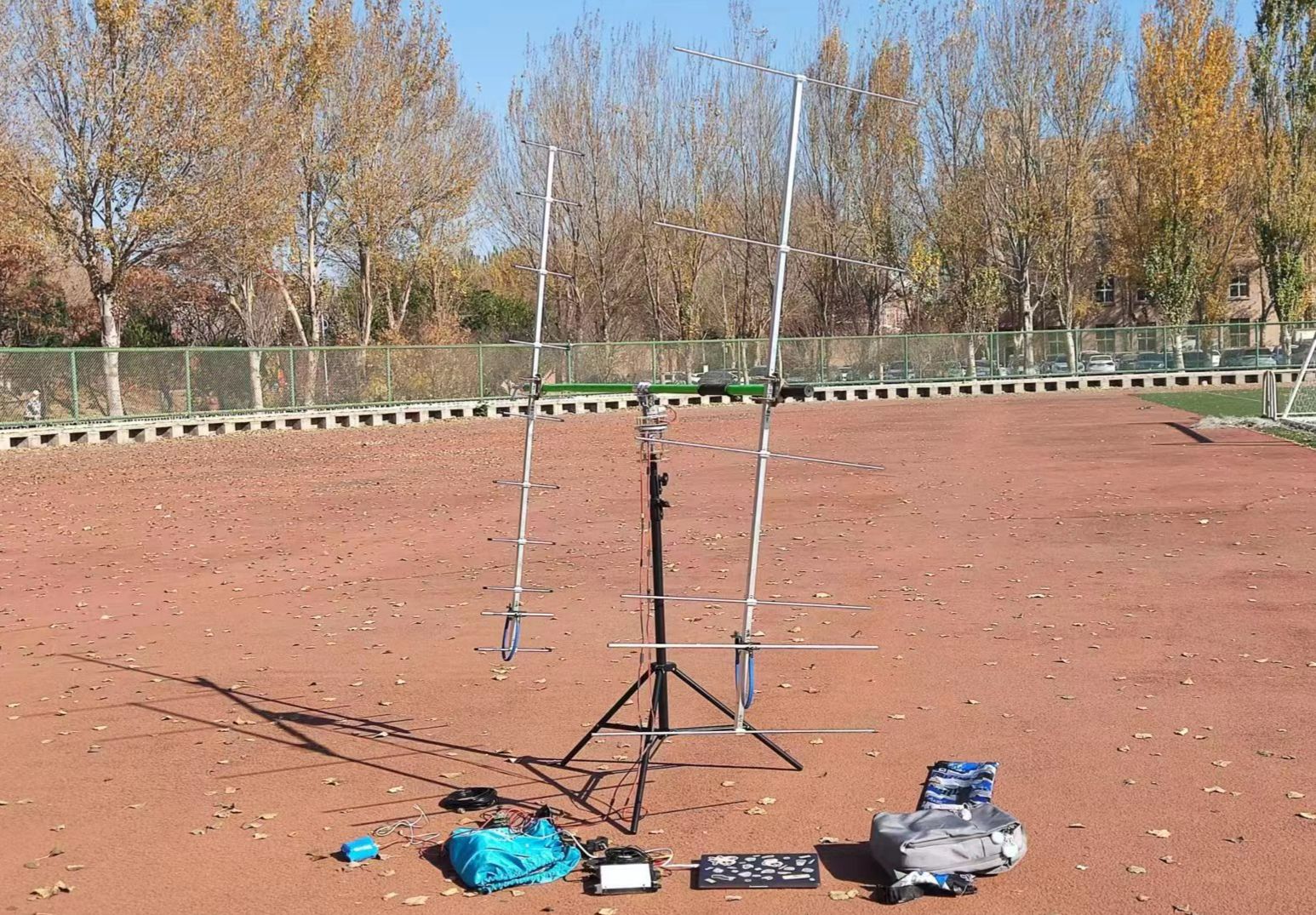
Physical Display


Design Considerations
1.The I2C address of BMI270 is 0x68 and the I2C address of BMM150 is 0x10.
2.The IMU Module and the BMM150 on the Yaw Module need to be welded either one (at present, because the code has not solved the azimuth angle calculation of the BMM150 under coordinate system transformation, the BMM150 on the Yaw Module should be welded)
Other
2023-09-22 Progress [First phase completed]: https://www.bilibili.com/video/BV16w41127GJ/
2023-09-13 progress: https://www.bilibili.com/video/BV1wN4y1X7ui/
2023-08-28 Progress: https://www.bilibili.com/video/BV1Ru411N7Sp/
2023-08-17 Progress: https://www.bilibili.com/video/BV1Bp4y1J7uz/
2023-08-19 progress: https://www.bilibili.com/video/BV1su4y1v7fq/
2023-08-21 progress: https://www.bilibili.com/video/BV1rz4y1u7r6/
Designed by BH2VSQ (from OSHWHub)
Design Drawing
 Empty
Empty
Comment