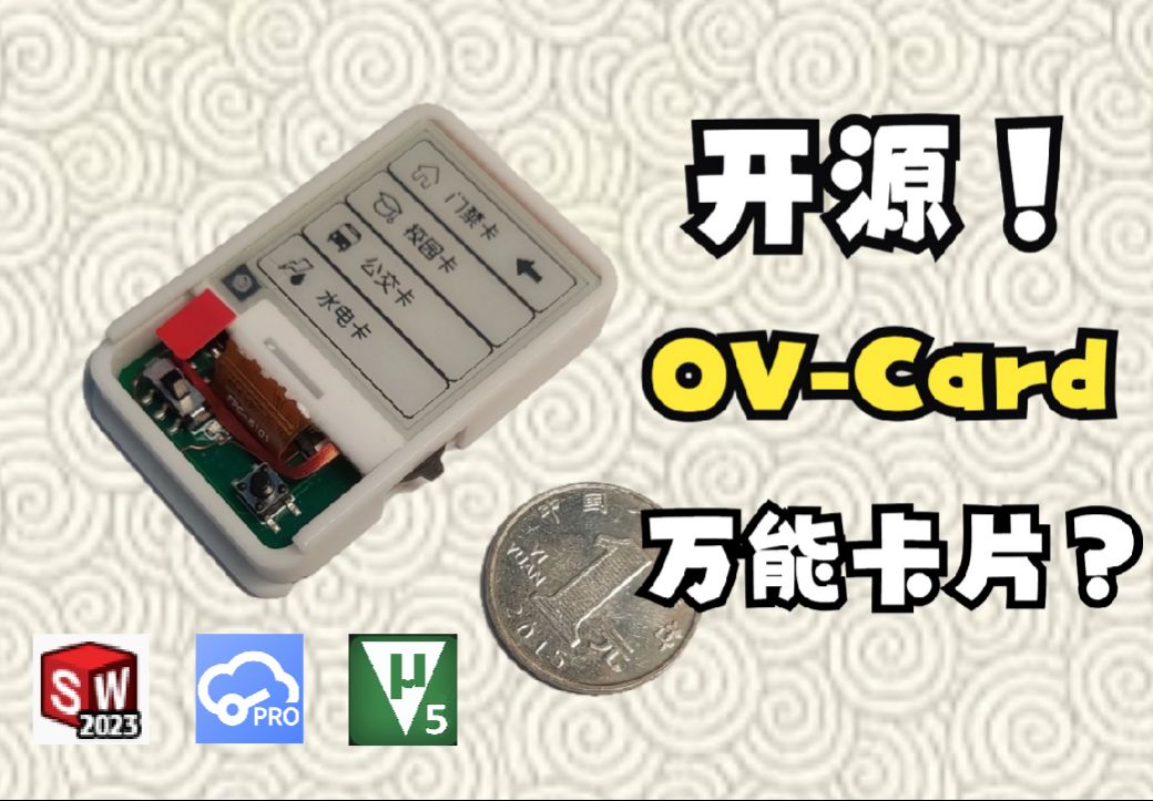
 Completed
The Universal Card OV-Card
PRO The Universal Card OV-Card
License
:CC BY-NC-SA 3.0
Description
Project Description
The overall hardware block diagram of the system is shown in the figure below. The main control uses STM32L051K8U6, the battery power supply uses TPS63020 design, and the display uses a 1.54-inch 200*200 ink screen, if you don't want to buy an ink screen, or want to use it for a long time, you can use the ultra-low power version, only use LED for display. As for card information storage, all information is stored in the EEPROM inside the MCU.
Note that the RC522 supports 14443, and this design only uses a UID card to implement the card emulation mode with the RC522.

Directions for Use
!!!!Note: Please switch the mode before powering on, and do not slide the switch to switch the mode when the power is on!!!!!
Hardware Operating Instructions:
1. Press the power on by pressing the button, and the power will be cut off when it is released.
2. Through the dial wheel switch, slide up and down after powering on, you can switch the selected position (i.e., switch card).
3. Switch the mode by slide switch. (Do not switch modes when powered on)
Switching Mode Description:
1. Slide to the left is the copy mode, after powering on, you can copy the external card in the selected storage location, for example, the access control card has been selected, just put the external card close to the back, you can write the card information to the selected storage location.
2. Slide to the right to the card simulation mode, after powering on, that is, the information is written into the IC card. As long as you keep the slide switch on the right, you can still swipe the card after power-off, that is, it will be read by an external card reader.

Design Principles
The RC522 was chosen for the design because it supports IEC 14443A/MIFARE. The functions it supports are as follows, there is a read-write card mode, but it does not support the card emulation mode, so this design has an external UID card, plus enable, to achieve the card emulation mode.

The functional block diagram and IC card information partition diagram are shown below. The NFC module reads the card number of the external IC card, i.e., the data of sector 0 and block 0 through the RC522, and then stores it in the EEPROM inside the STM32L051. The slide switch controls the opening and closing of the coil of the internal UID card, that is, the enable function is added, and the card number information stored in the EEPROM is written into the UID card through the NFC module, and the card copy function is realized.
Generally speaking, it is enough to copy the information of the 0 sector 0 block, such as the access control card, the campus card, and the water card, which are the card number information of the 0 sector 0 block of the identification card.


Hardware Description
1. The CR1220 used by the battery, if it is environmentally friendly, you can use the rechargeable ML1220, and you can recycle it when you run out.
2. The TPS63020 used in the power supply part uses the TPS63020 power save mode because the current is much less than 10mA. If you change to TPS63021, the feedback resistor needs to be changed there according to the schematic instructions.
3. In the PCB, the vias under the sliding button are used to solder the coil, as shown in the figure below. The reason why we don't draw another coil on the PCB is because the coil of the RC522 in the NFC part is too close to the coil of the UID card, and it will not be able to sense it and cannot read and write. I tried to draw the coil of the UID card on inner layer 1 before, but the NFC could not read or write.

Software Description
There are two versions of the code, one is a normal version with an ink screen, and the other is a low-power version that adapts to the LP board and removes the ink screen and replaces it with an LED.
If you need to change the ink screen to display the picture, you can directly use the image to convert the mold, here you can use Image2Lcd, the settings are as follows.

In the ImageData.c file in the .\BSP\EPaper file, you can change the gImage array, as shown below.

Other Considerations
When playing LP low-power boards, you can change the silk screen printing yourself and put it under each LED.
If the user is interested, he can change the interface diagram of the ink screen by himself. The picture can be converted to LCD to take the impression.
Note: Don't copy someone else's card, just copy your own card and be a good citizen!
Demo Video
Video link: https://www.bilibili.com/video/BV1Ju4y1q766
Repository Links
It contains all the information of hardware, software, and 3D printed shell.
GitHub repository: https://github.com/No-Chicken/OV-Card
QQ Group
QQ Group: 572216445

Designed by 不吃油炸鸡 (from OSHWHub)
Design Drawing
 The preview image was not generated, please save it again in the editor.
 Empty
Empty


Comment