© 2024 EasyEDA Some rights reserved ISO/IEC
Editor Version
×
recommended

Pro Edition

 Brand new interactions and interfaces
 Smooth support for design sizes of over 3W
devices or 10W pads
 More rigorous design constraints, more
standardized processes
 For enterprises, more professional users


Std Edition
 Easy to use and quick to get started
 The process supports design scales of 300
devices or 1000 pads
 Supports simple circuit simulation
 For students, teachers, creators


Completed
PRO
 TagCube, 5x7LED dot matrix custom business card supporting NFC wireless power supply
TagCube, 5x7LED dot matrix custom business card supporting NFC wireless power supply
License
CERN Open Hardware License
License: CERN Open Hardware LicenseMode:
Mode
Editors' pickEditors' pick
- 0
Update time:
2024-11-19 09:27:02
Creation time:
2024-11-19 01:48:28
Description
Description
Explain, NB means NFC is the Best (escape.
Notes on making boards
NFC antenna parameters are related to the board thickness. Please do not adjust the board thickness at will (it has been adjusted for 1.6mm). If you need to adjust, please use the official tool to recalculate the antenna parameters: NFC Antenna Tool , remember!
Board introduction
The design inspiration of this board comes from the official demo of LPC8N04 Development Board for LPC8N04 MCU , with the following main changes:
1.The redesigned board is in the shape of a business card and is divided into two sub-boards, NFC and debugging. The debugging sub-board can be removed when not in use.
2.For the convenience of wiring, the pins have been modified for the LED, but this does not affect the function of the demo (the source code needs to be modified and the firmware recompiled).
3.The official design uses 35 LEDs to form a dot matrix. Here I directly use a large-area 5x7 LED dot matrix (usually used in elevators), which has a better display effect.
4.The LED dot matrix uses a replaceable design, leaving space for the use of crown springs or claw springs. Of course, it can also be directly welded.
5.Multi-power supply design supports three power supply modes: USB, button battery and wireless power supply, which can be switched through the button switch.
More high-resolution images of the board are shown below.


How to use Demo
The use of Demo is divided into two parts, namely MCU program download and App installation.
Downloading the MCU program is relatively simple. You only need to download the app_demo.hex file in the attachment to the MCU (the firmware is compatible with the two bootloader versions of LPC8N04). The burning method depends on the tools at hand, ranging from the official MCUXpresso built-in tools to J-Link and the like.
To install the App, you need to download the corresponding Demo App on your mobile phone. For downloading and usage instructions, please refer to the User Manual for LPC8N04 Development Board. I will not go into details here.
Accessories purchasing advice
As for accessories, the LED dot matrix is mainly important. Of course, if you want to make a pluggable design of the LED dot matrix, you also need to use connectors such as crown springs and claw springs.
LED dot matrix
LED dot matrix needs to meet the following basic conditions:
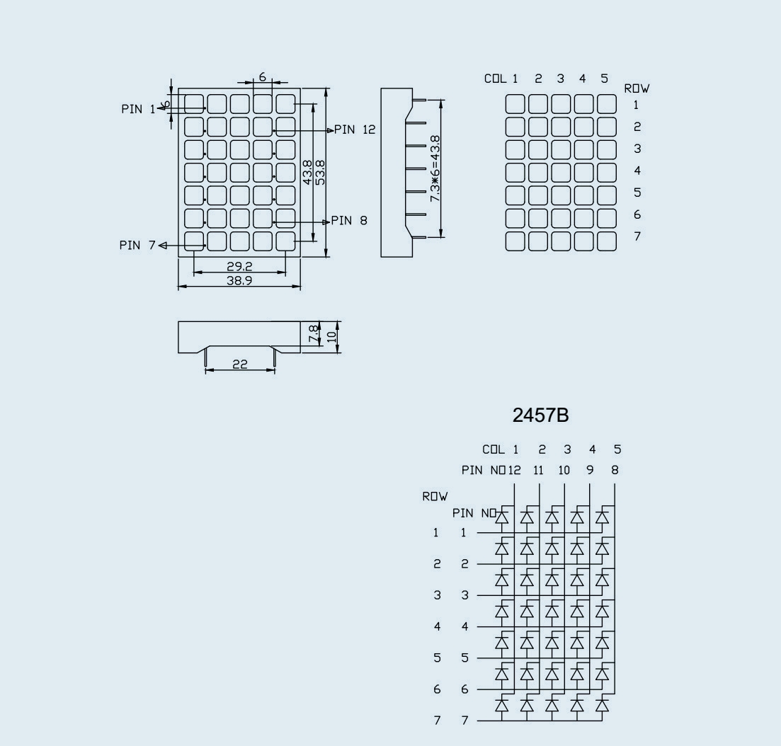
- Common anode ( 7 positive and 5 negative ), and the pin arrangement is as follows (the PCB leaves vacancies below PIN8 and above PIN12, which is compatible with the 7+7 design with two invalid pins)

- The size is about 39x54 mm2 , and the height is generally 10 mm.
- Pin spacing is 7.3 mm vertically and 22 mm horizontally.
- If you need wireless power supply, you can only choose red LEDs with lower operating voltages.
The purchase link is as follows:
https://item.taobao.com/item.htm?id=693466570477 (Affordable price, only red, you need to choose a common anode, and confirm with the seller whether the existing LED dot matrix pins are compatible)
https://item.taobao.com/item.htm?id=12995093575 (It is more expensive, available in red, blue and white, and is compatible with all existing models)
Crown spring/claw spring
This connector is quite expensive (after all, at least 12 are used), and is generally used for keyboard shafts. When purchasing here, please note that you need to select 0.5mm through holes . The options listed here are all compatible with current PCBs (hole inner diameter 1.04mm)
The purchase link is as follows:
https://item.taobao.com/item.htm?id=576197842803 (TS0.5Z via hole, welding required)
https://item.taobao.com/item.htm?id=559448570514 (MM0553,no soldering required)
Demo video
The following two videos demonstrate the use of demo, among which:
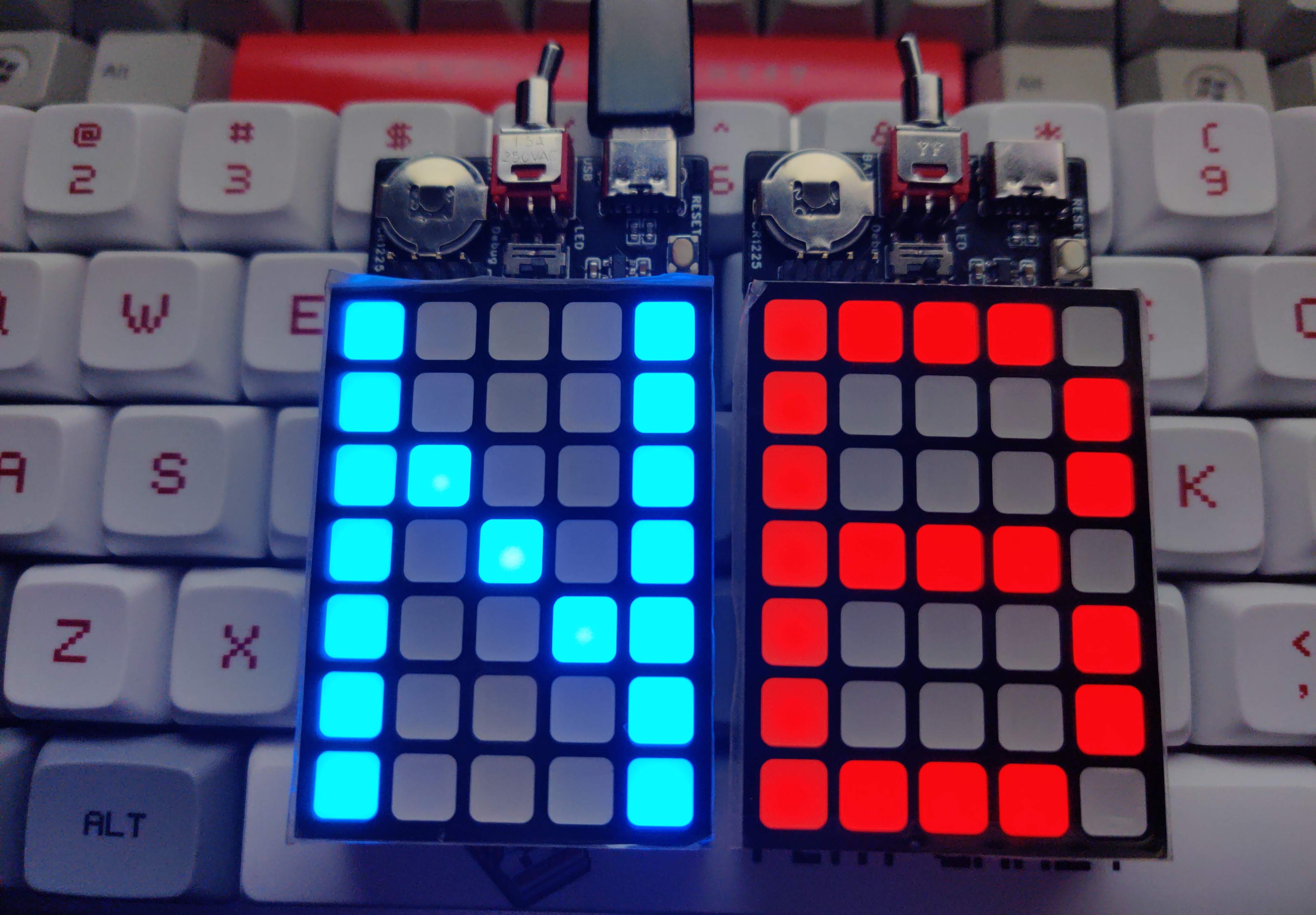
- The first video demonstrates the display effect of red and blue LED dot matrix. The red LED dot matrix is powered by CR1225 button battery, and the blue LED dot matrix is powered by USB-C interface.
- The second video demonstrates NFC wireless power supply, using only the power provided by the mobile phone's NFC to light up the LED dot matrix (the display effect is better in a dark environment).
Designed by metro (from OSHWHub)
Design Drawing
Design Drawing
schematic diagram
(
1
/
)
PCB
(
1
/
)
The preview image was not generated, please save it again in the
editor.
Related Projects
Change a batch
Loading...
Comment
Add to album
×
Loading...
reminder
×
Do you need to add this project to the album?


