

 Completed
STM32 digital multimeter
PRO STM32 digital multimeter
License
:GPL 3.0
Description
Design requirements
Design and manufacture a practical digital display multimeter that can measure voltage, current, resistance, etc.
(1) Measurable voltage range: DC 0~30V, error ±1%;
(2) Measurable current range: DC 0~2A, error ±1%;
(3) Measurable resistance range: 0Ω~100KΩ, error ±1%;
(4) OLED display is used, and the main control adopts STM32 series single-chip microcomputer;
(5) The power supply adopts +12V power supply;
(6) It can realize automatic switching of measuring range;
(7) Other parts of play;
System block diagram

Hardware design
1. Power circuit
This circuit is composed of two LM1117 LDO chips connected in series. The first stage converts the input voltage to a 5V output; The second stage converts the 5V voltage to 3.3V to meet the power supply needs of each module of the system.
2. Voltage detection circuit
Using one LM324 op amp, three channels are taken to form an amplifier, an attenuator, and a follower to suit different voltage level inputs. The op amp output is connected to the CD4052 analog switch for range switching.
3. Current detection circuit
The MAX4080 is used for the current sensing amplifier, which has a magnification of 20x. The range switching function is realized by selecting different sampling resistors through the relay.
4. Resistance detection circuit
The resistance measurement is realized by the resistance divider principle, and the voltage divider resistors of different ranges are selected through the MOS tube.
5. Other circuits
Including OLED display interface (OLED adopts Zhongjingyuan electronic 1.91-inch display), matrix keyboard interface, etc.
Software design
The initial configuration was performed using the STM32CubeMX tool. The main purpose of the logic code is to realize the control of the range switching circuit, the reading of the key status, the processing of the measurement results, and the display of the OLED screen.

Accuracy optimization and testing
Accuracy Optimization Scheme:
1. Use high-precision voltage divider resistors: 0.1% precision sampling resistors are selected for all voltage divider resistors.
2. Software enables self-correction: use HAL library functions:
HAL_StatusTypeDef HAL_ADCEx_Calibration_Start(ADC_HandleTypeDef* hadc)
3. Increase the number of ADC cycles: This design has low real-time requirements for measuring voltage, current, and resistance, so the number of ADC cycles can be increased as much as possible to improve the measurement accuracy, which has been set to the maximum value (239.5Cycles)
4. Software filtering: The design adopts a sliding window filter to ensure the filtering effect and real-time performance.
5. Linear fitting correction: Linear fitting is achieved by recording the reading value of the device and the reading value of the standard multimeter, and the linear fitting is achieved by the MatLab program. The fitting achieved the correction effect of the correlation coefficient of 0.9999981, and the accuracy was further improved.
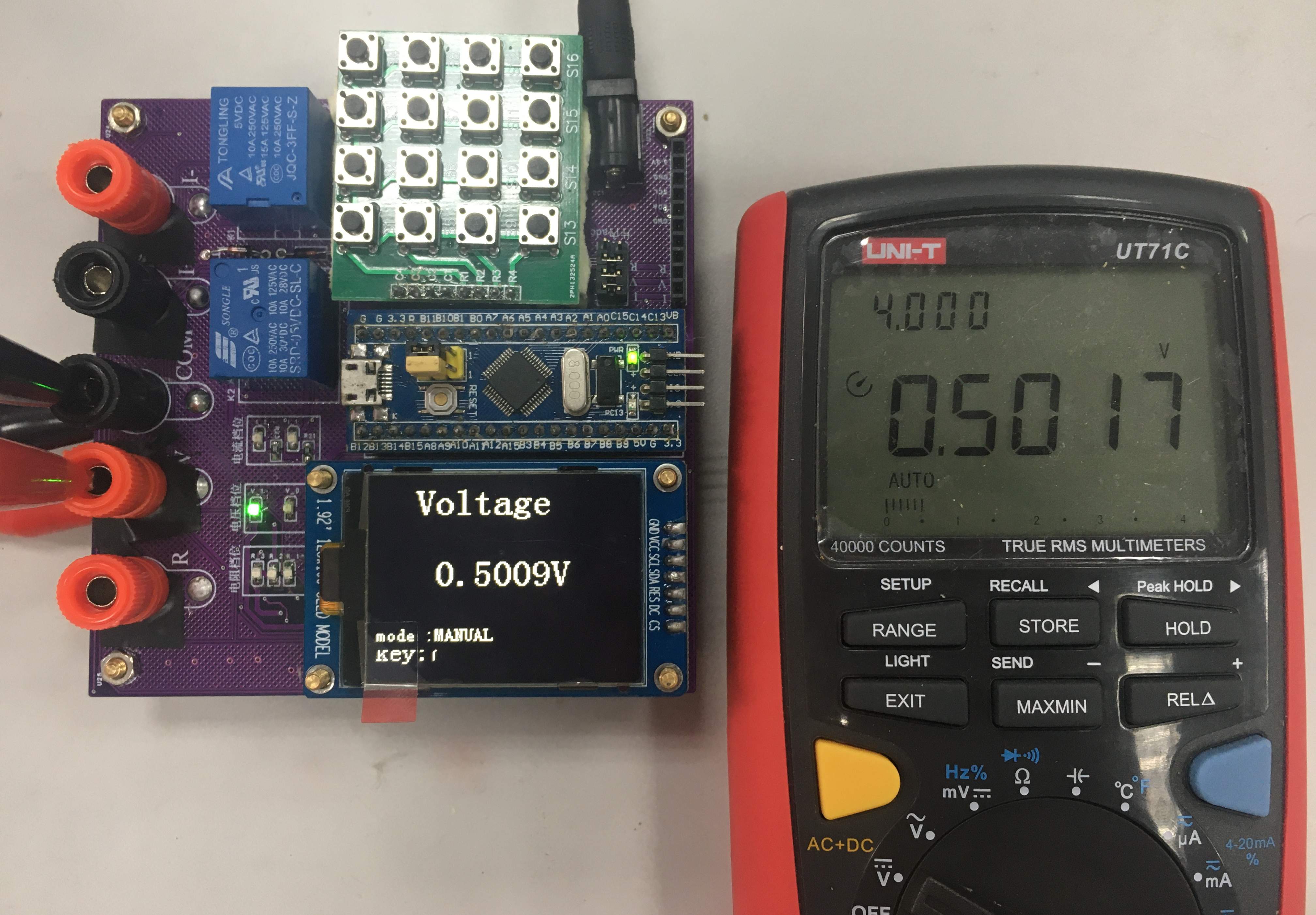
Test Results:
The test was averaged 20 times by comparing it with the UNI-T UT71C model multimeter.
|
Mode |
Average error |
|
Voltage |
0.74% |
|
Current |
0.96% |
|
Resistance |
0.85% |
The three modes measure the mean error statistics.


The feature introduction and demonstration are detailed in the video. STM32 AXF programming files are provided.
Designed by geekmwb (from OSHWHub)
Design Drawing
Intellectual Property Statement & Reproduction Instructions
This is an open-source hardware project. All intellectual property rights belong to the creator. The project is shared on the platform for learning, communication, and research only; any commercial use is prohibited. If your intellectual property rights are infringed on EasyEDA, please notify us by submitting relevant materials in accordance with the Rules for Complaints and Appeals of IPR Infringement.
Users must independently verify the circuit design and suitability when replicating this project. All risks and consequences are borne by the user, and the platform assumes no liability.
 Empty
Empty
Comment