

 Completed
Space-gesture Control [BlueGo]
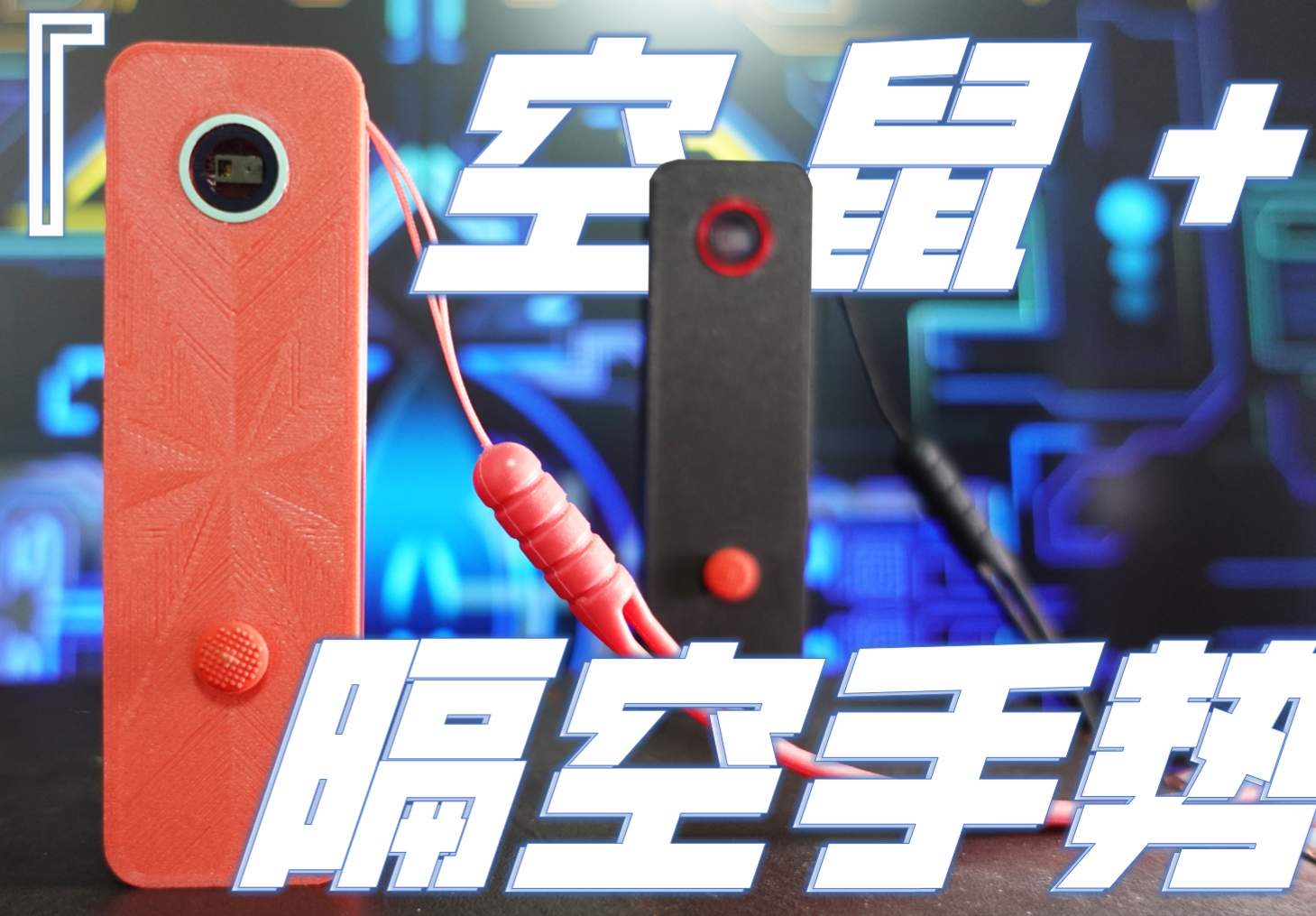
PRO Space-gesture Control [BlueGo]
License
:CERN Open Hardware License
Description
Changelog:
- Date: 23-10-20, Contents: 1. Uploaded the latest firmware (firmware burning (2023-10-20).zip), the latest firmware can support more mobile devices, and some bugs have been fixed; 2. Add some usage considerations (see end of article).
- Date: 23-10-24, Contents: 1. Uploaded the latest firmware (firmware flashing (2023-10-24).zip), fixed some bugs, and updated the operation guide; 2. Uploaded the latest BlueGO APP and fixed some compatibility issues and bugs.
- Date: 23-11-17, Content: Added QQ exchange group: 690317122 in the project introduction.
- Date: 23-11-20, Contents: Project introduction, chip selection and circuit principle introduction.
- Date: 24-03-07, Content: Added BlueGo V2 project connection.
- Date: 24-03-12, Contents: Added the latest firmware, fixed some bugs.
Project Introduction:
BlueGo is a BLE (Bluetooth Low Energy) HID peripheral, which is developed based on the ESP32 chip and integrates a gesture recognition module (PAJ7620U2), an inertial sensing chip (MPU6500) and a five-way button. In addition, it is equipped with a lithium battery management chip and a lithium battery for portability. With Bluetooth Low Energy, BlueGo can connect with a mobile phone, tablet, TV or computer, providing a variety of functions such as air mouse, gesture interaction and keyboard macros. Through the companion Android app, users can customize the functions of gestures and keys. The basic functions of this project have been completed, please wait for the function expansion and optimization~~
An enhanced version of this project has been completed: the universal Bluetooth peripheral [BlueGo v2].
In the process of BlueGo's forking, if you encounter any software and hardware problems, you can add a QQ group to communicate, QQ group: 690317122.
The project has been released in the radio 2023-9 issue, and friends who have magazines can see the more detailed content.

Video Introduction:
Function Introduction:
1. Air Mouse,the device uses a MPU6500 gyroscope to obtain the angle change by calculating the integral of the angular velocity of the Z/X axis, and converts it into the X/Y coordinate change of the mouse to realize the cursor movement. At the same time, the 3 keys in the five-way button are mapped to the left, middle, and right buttons of the empty mouse. The effect is as follows.

The device doesn't have integrated scrolls, but I used a clever way to map the rotation of the Y-axis to a mouse wheel. To use it, you'll need to turn your wrist left and right to roll the wheel back and forth. In order to avoid false triggering, a high trigger threshold is set in the settings, and the scroll wheel will only be triggered when the wrist rotation speed exceeds this threshold. The effect is as follows, but it is a bit of a trick (manual funny).

2. Gesture interaction, the device uses the 7 gestures of the PAJ7620, which are mapped to the phone's up, down, left and right, finger tap and back, etc., so that the phone can be controlled with gestures. This is very convenient in situations where it is inconvenient to touch the mobile phone for eating, cooking, cleaning, etc. Among them, the air operation of short video software is a typical application, and the effect is as follows.


3. Keyboard macro, the device also supports simple keyboard macro functions, and presets a variety of keyboard keys and key combinations. These actions can be mapped to five-way buttons or 8 gestures to operate a phone or computer as a peripheral. Common application scenarios include PPT remote control, gesture control virtual desktop, remote control mobile phone photography, etc.
4. Custom function, I have developed an Android App for this device (see the attachment "bluego.apk at the end of the articleAfter the device is connected to the App through Bluetooth, it can realize the free switching of various functional modes and the customization of functional modes. Gestures and buttons can be mapped to a variety of preset actions for more gameplay. At present, only some mobile phone touch gestures, keyboard keys, shortcut key combinations and electronic device operations are preset in the device. Capable users can design more touch gestures and add more shortcuts to achieve more interesting functions, as shown in the figure below. Open the imagination and it will have an infinite number of uses.


Module Architecture:
The hardware part mainly includes the main control board, GY-PAJ7620 module and lithium battery. The main control board is designed for itself, including the main control MCU ESP32-PICO-V3-02, the inertial navigation unit MPU6500, the five-way button and the charging management chip TP4056. The GY-PAJ7620 module is a self-purchased module, which communicates with the main module through the IIC bus. The power supply adopts 3.7V 200mah single lithium battery. See the figure below for details.

Chip Selection:
First of all, I want to start with the main control chip, I want to choose a mainstream and feature-rich chip, so that more references and codes can be found on the market, and preferably Bluetooth Low Energy is also integrated. As a result, the ESP32 series of chips seems to be the obvious choice. The ESP32 series chips have been very mature and abundant after several years of development. After careful screening, I finally chose ESP32-PICO-V3-02. Based on the ESP32 (ECO V3) design, the chip is a system-in-package (SiP) product that provides full Wi-Fi and Bluetooth capabilities. It integrates all peripheral components such as crystal oscillator, Flash, PSRAM, filter capacitor, RF matching link, etc., in a single package, and can operate without additional peripheral components. This design saves a lot of trouble with circuit design and testing, and it is definitely the safest and most reliable option for me as a first-time circuit designer.
When it comes to gesture recognition sensors, there are relatively few options on the market, and the PAJ762U2 is one of the more outstanding ones. PAJ7620U2 is a gesture recognition chip developed by PixArt, which integrates an optical array sensor unit, which can quickly and accurately sense and process the input signal. Built-in light source and ambient light suppression, can work in dark or low-light environments. It supports up, down, left, right, forward, rear, clockwise rotation, counterclockwise rotation and waving gesture recognition, as well as supporting functions such as object proximity detection. Users can obtain the results of target raw data and gesture recognition through the I2C interface. PAJ762U2 is incredibly powerful, with the sensitivity and accuracy required by our air control devices.
To achieve the flying squirrel function, you need to choose a high-precision gyroscope chip, and after comparison, I chose MPU6500. It integrates a 3-axis MEMS gyroscope, a 3-axis MEMS accelerometer, and a programmable digital motion processor, the DMP. The chip's gyroscope has programmable sensing ranges of ±250, ±500, ±1000 and ±2000°/sec, with noise levels as low as 0.01 dps/√Hz. It communicates with the MCU via an IIC interface and has a clock of up to 400KHz. This fully satisfies the needs of flying squirrels for precision and response rate.
Circuit Principle:
1. Power Supply Circuit:

This device uses a single 3.7V lithium battery as the power supply, which is stepped down to 3.3V by an LDO chip (U4RT9013-33GB) to power each module. The positive terminal of the lithium battery is connected to the BAT+ pin, which is connected to the current input pin VIN of the LDO and the chip enable EN pin through a slide switch, which controls the current input and the enable state of the chip. The step-down 3.3V current is output via VOUT, filtered by C8, and supplied to each module. The negative pole of the battery can be connected to any GND pin. The lithium-ion battery is charged using the TP4056, a high-performance single-cell lithium-ion battery constant-current/constant-voltage linear charging chip. The 5V current input through the USB interface is filtered by R2 and C1 and then enters the chip's VCC pin, and the chip's enable pin CE is connected at the same time. When the USB port is plugged in, charging can start automatically. The chip outputs a constant voltage current of 4.2V, which is output through the BAT pin, filtered by C2, and flows into the positive terminal of the battery. The PROG pin is used to control the charging current, and here a 1.2KΩ resistor is grounded so that the chip can output 1000mA. The TEMP pin is used to detect the battery temperature, which is not used here, and is directly grounded. CHRG and STDBY are two open-drain status indication outputs. When the charger is in the charging state, the CHRG pin is pulled to a low level, LED1 is on, in other states CHRG is in the high resistance state, and LED1 is off; When the battery is charged, the STDBY pin is pulled low and LED2 is on, and in other states the STDBY is in a high-impedance state and LED2 is off.
2. MCU Main Control Circuit:

Since the ESP32-PICO-V3-03 chip already has a high level of integration of crystal oscillator, Flash, PSRAM, and RF matching circuitry, its external circuit design can be very simple and efficient. The following is the specific design of the power supply section and the antenna part:
- Power supply part:
The 3.3V current from the LDO output passes through two filter capacitors (C3, C9) and is connected to the VDDA, VDDA3P3, VDD3P3_CPU, and VDD3P3_RTC pins to meet the power supply needs of the chip. In order to ensure that the chip is powered up properly, an RC delay circuit is used at the EN pins. According to the recommended values in the official documentation, elements with R = 10 kΩ and C = 1 μF were used. Such a design can stably enable the chip to start up after powering up.
- Antenna part:
While the chip already has an integrated RF matching link that allows direct connection to various antennas, for added stability, I added an additional π matching circuit to connect it to a ceramic antenna. This design not only ensures the performance of the antenna, but also effectively saves PCB space. Other function pins are used to connect peripheral chips or pinouts to facilitate subsequent function expansion. Through the above simple and efficient circuit design, the power supply stability and antenna performance of the ESP32-PICO-V3-03 chip are ensured, so that the performance of the whole device is optimized.
3. IMU Circuit:

The 3.3V current at the LDO output is connected to the MPU6500's power supply pin, VDDIO, and the chip is also enabled by connecting to the nCS chip select pin. In addition, the AD0 pin is used to set the lowest address bit of the chip, which is grounded here, and the IIC address of the chip is set to 1101000. To meet the requirements of the chip, to attach a bypass capacitor to the REGOUT pin, a capacitance of 100nF is selected. Finally, the SDA/SDI and SCL/SCLK pins need to be connected to the SDA and SCL pins of the main chip for IIC communication. With these connections, the MPU6500 can communicate stably and efficiently with the main chip.
4. Gesture Recognition Circuit:

The gesture recognition adopts the ready-made module GY-PAJ7620, which is pinned to the main module as follows: VIN (power supply pin): can be directly connected to the VCC33 power supply of the main module to provide power to the gesture recognition module. I2C communication pins: SCL and SDA are connected to SCL1 and SDA1 of the master module respectively to achieve IIC communication with the master module. INT (Interrupt Output Pin): The I37 pin connected to the MCU outputs a low level to trigger an interrupt when the gesture is recognized, notifying the main module that a gesture has occurred.
GND (Ground): Connect to any GND pin of the main module. Through this connection, the master module can interact with the gesture recognition module through IIC communication, and the connection of the interrupt pin enables the master module to perceive the occurrence of gestures in real time, so as to operate and process the gesture accordingly.
5. Five-way button circuit:

The button circuit uses an ADC scheme that uses only one pin of the MCU. By sampling the voltage when the button is pressed, the device can recognize the status of the five buttons. The common pin (COMM) of the button is connected to the IO27 pin of the MCU as the ADC sampling input. The button pins in each of the five directions are connected to different nodes of the 6 equal series resistors. When different keys are pressed, the MCU can judge the state of the keys by the sampled voltage value. When there is no key, the IO27 is grounded via R13. This simple voltage divider circuit not only realizes the 5-key differentiation but also saves IO resources, and the wiring is simple and effective.
6. External Interface Circuit:

The device uses a Type-C USB port, which makes charging more convenient because the Type-C port does not need to distinguish the direction of the interface. The USB port only uses two pins, VBUS and GND, for power supply functions, and the other pins are not used. In addition, all pins of the main chip are led out through two 15-pin headers for easy connection to peripherals. The pin header is designed so that the device can be expanded with more functions and connected to various external modules or sensors, thus increasing the flexibility and scalability of the device.
Device Code:
- ESP32 code (based on ESP-IDF): Geek Fantasy/bluego-esp32 (gitee.com), GeekFantasy/bluego-esp32 (github.com)
- Android code (see attachment for APK installation): Geek Fantasy/bluego-android (gitee.com) , GeekFantasy/bluego-android (github.com)
Equipment materials and assembly:
- The gesture recognition module GY-PAJ7620 can be purchased from Taobao.
- PAJ7620 The front mounted lenses and red frames of the device are the same as those of the Apple 11 Pro/Max and can be purchased from here.
- Lithium battery 200 mAh, size: length * width * thickness: 30 * 20 * 4 (unit: mm) can be purchased from Taobao.
- The button cap uses the classic red dot navigation key on the Thinkpad (which feels good) and can be purchased from here.
- The assembly needs to use 5 M1.6*8mm socket screws, which can be bought from here.
- If you need the same lanyard, you can buy it from here.
- The shell of the device is printed by itself using 3D FDM, if you use 0.12mm printing, the installation accuracy is not bad, and other accuracy should be fine. The shell is designed using SOLIDWORKS, and the relevant documents are attached at the end of the article.
- The wiring diagram of the device is as follows.

- The module installation sequence is shown in the figure below.

Firmware Burning:
- The program requires a USB-to-UART device, because the motherboard space is limited, and there is no integrated USB-to-UART chip. There are a lot of USB to UART devices, and I use this one (USB to UART).
- Students who use VSCode + ESP-IDF can download the source code and compile and burn it.
- You can also use the ESP32 official burning tool, firmware and specific steps, please refer to the attachment for the latest version of firmware burning.
Notes:
- When forking, it is recommended to use a 1mm thickness for the PCB, which can be perfectly matched to the housing.
- After the device is turned on, you need to immediately put the device still for a few seconds to allow the MPU6500 to calibrate itself, otherwise the pointer will drift in the air mouse.
- If the new mode doesn't work immediately after the device switches working modes, you can try restarting BlueGo, unpairing BlueGo Bluetooth on the main device, and then reconnecting it.
------------------------------------------------------------------------------------------------
If you think this project is not bad, please don't hesitate to like and collect, thank you~~
------------------------------------------------------------------------------------
Designed by Geek Fantasy (from OSHWHub)
Link:https://oshwhub.com/geekfantasy/fei-shu-shou-shi-cao-kong-wai-sh
Design Drawing
 Empty
Empty
Comment