

 Completed
Smart gun [CyberGun]
PRO Smart gun [CyberGun]
License
:CERN Open Hardware License
Description
Project Description
The main purpose of this purpose is to intelligently upgrade a soft egg (sponge soft egg) launcher (Semberon Gecko 2.0). An ESP32-Pico-D4 device was installed on the transmitter with a 1.33-inch TFT screen with integrated IMU: MPU6050 and 8 Hall sensors. The IMU is used to interact with the system using somatosensory, and the Hall sensor is used with a magnet to detect the bomb load and loading status. Using the ESP32 integrated Bluetooth and Wifi, it can interact with other systems to complete data reporting.
Bilibili video:I made a smart gun and developed a supporting smart application, I'm afraid I can't play _Bilibili _bilibili in the game
Functions include: ammunition load detection, loading and firing detection, shooting stability detection, gun stability training, motion status monitoring, etc.
Function introduction


- Application Switching -- The device is designed with only a top button and does not use a touch screen, so it relies on the IMU of the device to sense the status of the device to operate. To switch between applications, you need to tilt the transmitter left and right, and the preset application swipes across the screen at once, straightens the screen, and presses the button on the device to enter the application.

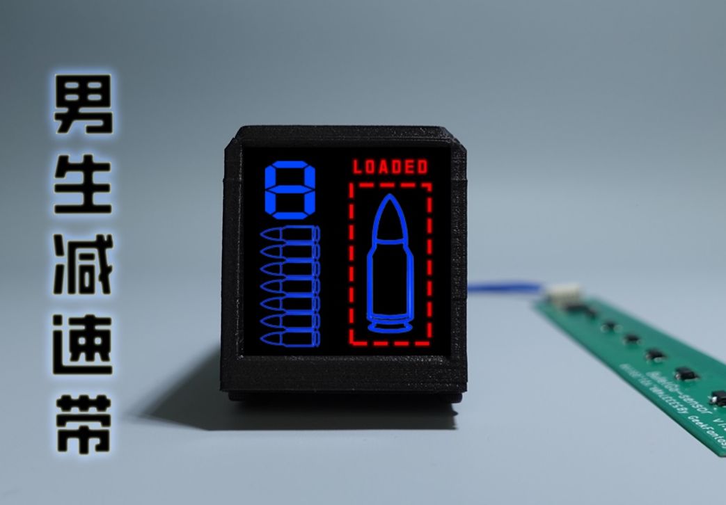
- Ammo Display & Loaded Firing Status Detection -- Enter the app, the ammo level and logo are displayed on the left side of the screen, and the loading and firing status are displayed on the right side. After loading the magazine, the device detects whether the magazine is loaded through the bullet detection circuit, and if there is a bullet quantity, it detects the ammunition volume again. At the same time, the machine will also detect the loading state, and when the loading and firing states are switched, a preset animation effect will be displayed. Green is unloaded, and red is loaded.

- Shooting Stability Detection - This application is used to show the range of horizontal and vertical pointing of the device within 1 second before and after the trigger is fired, and to show the stability of the shot with a 2-axis graph. The flatter the curve, the more stable the gun is when firing. This application only displays the data, and the data collection is done in the bullet display interface. The device records the last 5 shots, with the numbers 1-5, with 1 representing the most recent shot.

- Gun Stability Training -- This app is for training, after entering the app, it will count down to 3 seconds, and after the countdown is over, a target and a green or red dot will be displayed on the screen. The dot will change position according to the direction of the emitter, and the dot is green when it is near the center of the target, indicating stable aiming; When it turns red, it means that the emitter is pointing away from the original direction. When training, you need to work hard to keep the dot in the center of the target. The upper left of the screen is the timer, the upper right is the real-time score, the longer you keep the dot in the center position, the higher the score, and vice versa, the lower the score.

- Motion status monitoring -- after entering the application, the device starts the Wifi server, the device screen displays the server address, after using the computer to connect to this address, run the computer script, you can display the 3-axis acceleration curve in real time, and the motion state of the person holding the transmitter can be judged through the acceleration curve.

Project progress
Hardware: Completed, see attachment for shell 3D files
Software: Completed Source code: GeekFantasy/BulletGo (github.com).
Design Principles
The whole project is divided into 3 parts, the main control board, the sensor board and the programming board, as shown below. The main control board integrates the MCU, MPU6050, LCD and battery management chip to run the main control program; The sensor board integrates an 8Bit GPIO expansion chip, which is connected to the motherboard through IIC, and the 8 GPIOs are connected to 8 Hall sensors respectively to detect the number of bullets and loading status; The programming board integrates a serial port chip and an automatic programming circuit, and the program programming and serial port communication of the main control board are connected to the main control board through the UART bus.

Circuit principle
- Main control board circuit principle:
The main controller uses the ESP32-PICO-D4, an ESP32-based system-in-package (SiP) module that provides full Wi-Fi and Bluetooth ® functionality. Measuring just 7 mm × 7 mm × 0.94 mm, the module occupies the smallest overall PCB area and has integrated a 4 MB Serial Peripheral Interface (SPI) flash. So the peripheral circuitry can be very simple, and more devices can be integrated in a relatively small area. The CP-RX/TX pin is connected to the serial chip for printing logs and programming programs. IO0 and EN pins are linked to the OH programming board, which is used to control the chip to switch between programming and LOG modes. LCD-BL/DC/MOSI/SCK/RES is used to control the LCD display driven to ST7789. The GPIO35 connects a unique button for entering and exiting the app. SEN-INT/SCL/SDA is used to connect to a GPIO expansion chip on the sensor board, which can obtain the bomb load and detect whether it is loaded. MPU-INT/SCL/SDA is used for communication with MPU6050 and somatosensory interaction of user applications.

- Principle of bomb load and loading state detection circuit:
This circuit is located on the sensor board and is mounted on the side of the launcher's magazine. In order to reduce the number of lines with the main control board, an I2C interface GPIO expansion chip, NXP's PCA9554PW,118 , is used here Expand 8 GPIOs and connect 8 Hall sensors respectively. Seven of the Hall sensors are positioned with a 0-6 bullet load and a circular magnet fixed on the pallet plate to trigger the Hall sensors at different positions. As the amount of ammunition decreases, the magnet moves upwards in turn, triggering Hall sensors at different positions, and PCA9554W reports the GPIO status, and the main controller can collect the bomb load. An additional Hall sensor is located at the snap of the bolt and senses a magnet mounted on the bolt to determine whether it is loaded.

- Programming board circuit principle
The space of the main control board is limited, so the programming board is processed independently, mainly used for program programming and serial communication. CP2102 is used with two transistors to realize automatic program programming and automatic switching of LOG mode.

Assembly Steps:
1. Assemble and test the hardware section as shown below.


2. Fix each part of the hardware on the disassembled transmitter according to the wiring diagram, and fix it with hot melt adhesive or other glue (the blue part in the picture is used to cover the key parts, otherwise it cannot be uploaded if it is identified as a gun).

3. Follow the diagram below to install the Hall Sensing Trigger Magnet.

4. Assemble the launcher, test it, and you're done.
Device Code:
The firmware code is developed on the basis of the HoloCubic_AIO of the open source project: ESP32 code (Arduino): GeekFantasy/BulletGo (github.com).
Materials & Assembly:
- PCB: 3 circuit boards, main control board Main_v2.1 (board thickness 1.2mm), programming board Prog_v2 (board thickness 1.2mm) and sensor board Sensor_v2 (board thickness 0.6mm or FPC)
- Screen:LCD 1.33 inch 240X240, ST7789 driver, soldered 12Pin bare screen, Taobao-Zhongjingyuan Electronics
- Connecting wire: 3 circuit boards are connected through interface terminals, and the terminal connection wires need to be made by themselves, which can be purchased in LCSC
- Battery: 3.7 volt lithium-ion battery, model - 902030 500mAh (thickness: 9mm, length: 30mm, width: 20mm) Please choose by yourself (the one I purchased before has been removed from the shelves)
- Softegg Launcher: All devices need to be integrated into the Gecko 2.0 Softegg Launcher. You can buy it on Taobao, search for keywords: Semberon Gecko Launcher 2.0.
- Main control shell: you need to print it by yourself, see the attachment for the model.
Firmware Burning:
1. Programming with IDE: The program is developed using PlatformIO, and the program can be downloaded and burned directly after compilation.
2. Use the ESP32 Burning Tool: Available later.
Notes:
- When proofing, please pay attention to the thickness of the main control board Main_v2.1 1.2mm, the sensor board Sensor_v2 0.6mm FR-4 board or use FPC (can not be reinforced), too thick will not be installed.
- At present, the connection between the sensor and the main control part is not specially handled, and the wiring harness will leak. If you don't mind, you can wait until there is a solution before reproducing.
References:
- 稚晖君's HoloCubic(Adress)
- ClimbSnail's HoloCubic_AIO (Adress)
Designed by Geek Fantasy (from OSHWHub)
Link:https://oshwhub.com/geekfantasy/cyberblaster-softegg-launcher-upgrade
Design Drawing
Intellectual Property Statement & Reproduction Instructions
This is an open-source hardware project. All intellectual property rights belong to the creator. The project is shared on the platform for learning, communication, and research only; any commercial use is prohibited. If your intellectual property rights are infringed on EasyEDA, please notify us by submitting relevant materials in accordance with the Rules for Complaints and Appeals of IPR Infringement.
Users must independently verify the circuit design and suitability when replicating this project. All risks and consequences are borne by the user, and the platform assumes no liability.
 Empty
Empty
Comment