

 Completed
Simple Battery Internal Resistance Tester
PRO Simple Battery Internal Resistance Tester
License
:GPL 3.0
Description
project Description
Design a low-cost simple battery internal resistance tester with open source software and hardware.
Open-source Protocol
GPL 3.0
Project-related Features
Measure the internal resistance of the battery, the range is 1 mOhm to 100 ohms, divided into 5 gears, 0-10 mOhm, 10-100 mOhm, 100-1000 mOhm, 1-100 ohms, 10-100 ohms, button 2 to switch gears.
Project Properties
This project is the first public and is my original project. The project has not won an award in another competition.
Project Progress
The project has been completed.
Design Principles
The single-chip microcomputer SPWM is filtered by RC to generate a 1KHZ sine wave.

Then enter the constant current circuit, divided into 100 mA and 10 mA two gears, 100 mA sampling resistance is 10 ohms, 10 mA sampling resistance is 100 ohms, through the MOS tube and 4053 analog switch switching.

The following is to isolate the DC voltage of the battery through capacitors, and connect it through the Kelvin clip, note that the HC and LC wires should be wound together, and the HP and LP wires should be wound together, otherwise the magnetic field generated by the HC and LC wires will be coupled to HP and LP. HC, HP one clip, LP, LC one clip, don't make a mistake!

Enter the differential amplification circuit through the 104 ampere direct capacitor, and behind the differential amplification circuit is 1, 10, 100, 1000 times adjustable amplifier, first attenuate and then amplify, and finally the sine wave is raised to 1.65V to enter the single-chip ADC port.

The power supply section samples a 9-12V input, the 7805 generates +5V, the LM2596 generates -5V, and the 10 ohm and 470UF capacitor RC filters to power the amplifier circuit.

The MCU uses inexpensive STM32F030F4P6.

The 1602 that is easier to buy for display sampling.

Software Description
The software is relatively simple, ADC sampling rate 1MHZ to collect 1KHZ sine wave, collect 1000 points, then DFT to calculate the real part of the virtual part, and then into the 200-point filter, filter the amplitude of the square root, the amplitude multiplied by a value to obtain the resistance value of the measured resistance.
The open source address of the software: https://github.com/yjmwxwx/stm32asm/tree/master/gcm0/nei_zu_yi
The software is all open source, looking forward to the improvement of netizens, the program is written in pure assembly, and the compiler is ARM-NONE-EABI.

Enter make and you're ready to compile.

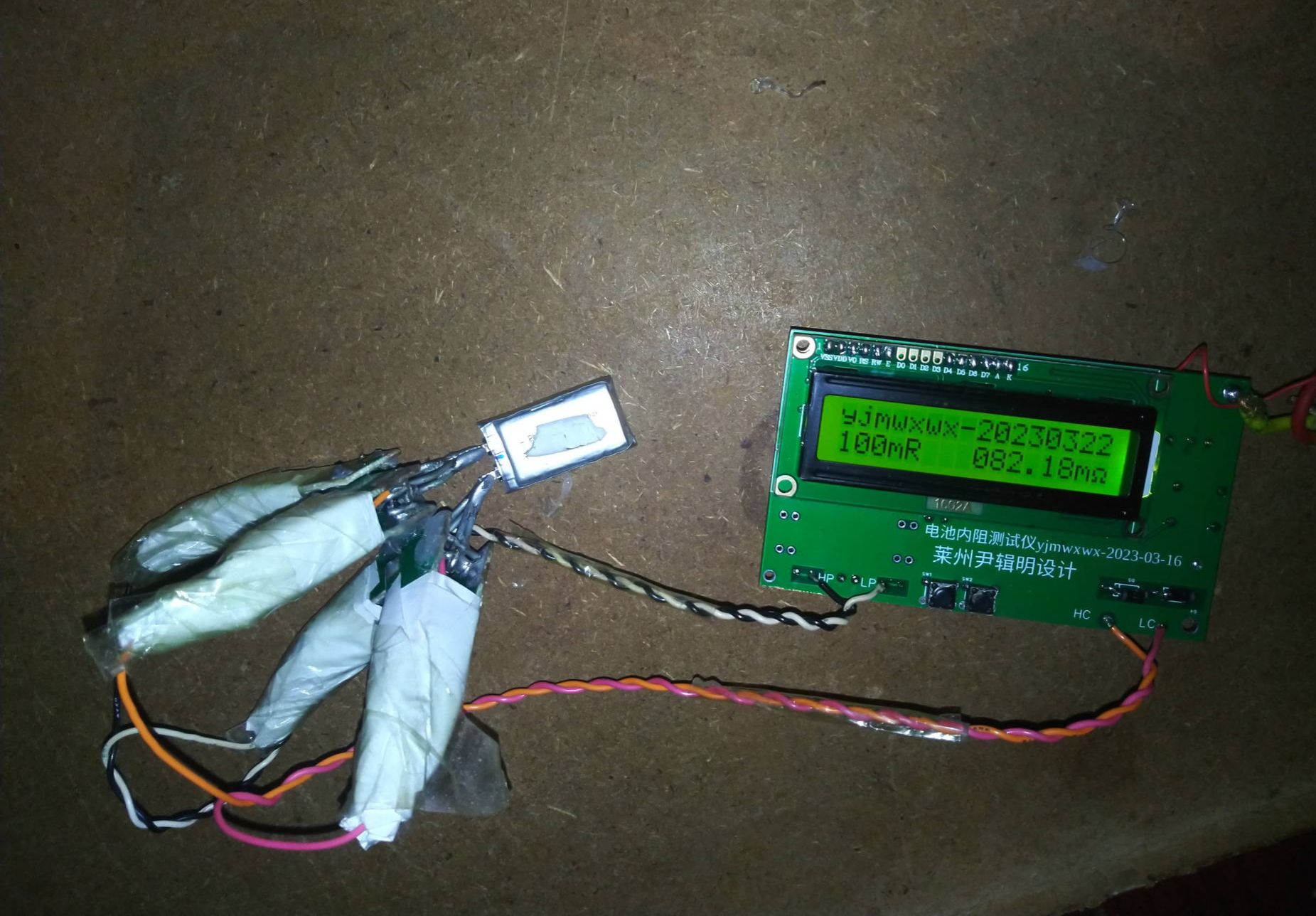
Physical Display
Measure small lithium batteries.

Front

Reverse side


Clip

Design Considerations
It is not suitable for battery power supply, and of course I don't care that I can change it to battery power by myself.
Other
Front and back video of the board
The clip is short-circuited, press button 1 to enter the short-circuit clearing mode, by adjusting the addition and subtraction of button 1 and button 2 to make the reading 0, then press and hold button 1 while pressing button 2 to enter the next gear, all clearance is completed, and it will be automatically saved to FLASH after the display is completed. Press button 2 do not let go, and then press button 1 to enter the calibration mode, such as calibrating the 0-10 milliohm file on the 10 milliohm resistance, through the key 1 and key 2 plus and minus to adjust to 10 milliohm, press and hold the button 1 at the same time, and then press the button 2 to enter the next gear, all the calibration will be completed and saved to the FLASH.
The data refresh rate is reduced to 4 readings per second, which is still a big jump.
Data refresh drops to 4 video refreshes per second
The picture below is calibrated with a 0.5 mOhm resistance in the 10 mOhm range, and it can be seen that more than 0.5 mOhm is larger, less than 0.5 mOhm is small, and the linearity accuracy is not good.
Measured pictures from 0.1 mOhm to 10 mOhm.


Change the ADC sampling rate to 100KHZ, the reading is more stable, and the linearity is better.
Video sampling rate 100KHZ reading stability linearity is better.
Below is the result of a sample rate of 100KHZ.


20230404 update
Battery-powered version of the video
Drew a battery-powered version of the PCB.


2023-04-11 Updated the program and circuit of the reduced power version
Reduced power version test video
As long as the circuit is replaced with three 100 ohm sampling resistors in parallel, and the 100 ohm sampling resistors are replaced with three 1K ohm parallels, the power amplifier part can only use two transistors, and the other two in parallel can be removed.
The program is changed to 33333 words display, gear 0-33 mOhm (33.3 mA), 33 mOhm -333 mOhm (33.3 mA), 333 mOhm - 3.33 Ohm (3.33 mA), 3.33 Ohm - 33.3 Ohm (3.33 mA), 33.3 Ohm - 333 Ohm (3.33 mA) The stability is relatively poor, and the reading jumps largely.
Now the calibration method is relatively simple, and the calibration is too slow to press at a time, and some people are willing to imitate it before writing the linearity calibration program. Now the calibration method wants to the lowest gear microohm level quasi to clamp first, such as 10 milliohm after alignment, before calibration advanced zero mode clearing, and then clamp such as 200 microohm this time can not adjust the calibration mode, to adjust the short circuit zero mode, adjust to the same size as 200 microohm, calibration mode adjustment is relatively slow, be patient.

Measure 100 μohm resistance.

Measure 200 microohm resistance.

Measure 300 microohm resistance.

Measure 500 microohm resistance.

Designed by yjmwxwx (from OSHWHub)
Link:https://oshwhub.com/yjmwxwx/jian-yi-dian-chi-nei-zu-ce-shi-y
Design Drawing
 Empty
Empty
Comment