

 Completed
Retro desktop VFD clock
PRO Retro desktop VFD clock
License
:CC BY-NC 3.0
Description
Project Description
The pleasing display effect of the VFD screen must have been seen by friends who clicked on this project. This project is my accumulation in the process of learning ESP32, based on FUTABA's VFD screen (13-ST-GINK) + ESP32-C3 A retro desktop clock made for main control, which obtains Internet time and local temperature and humidity display through 2.4G wifi networking (independent wireless temperature and humidity sensor, which can be set to date display without using the temperature and humidity sensor).
Clock size: 117*27.2*26.7mm
The clock is powered by 5V. The average operating current at maximum brightness is about 280mA. The instantaneous current when the buzzer sounds is 700mA. It is recommended to use 5V1A or an adapter with a stronger output current for power supply.
The average current is about 84mA when the display is turned off during nighttime standby.
Open Source Agreement
Creative Commons License-Attribution-NonCommercial.
Project Related Functions
Function 1: WIFI networking HTTP to obtain the Internet time and display it.
Function 2: The wireless temperature and humidity sensor obtains temperature and humidity, and can be placed anywhere in the room without metal shielding ( use my open source wireless temperature and humidity meter )
Function 3: Automatic brightness adjustment.
Function 4: Temperature and humidity abnormality alarm.
Function 5: Night display off.
Project Properties
This project is made public for the first time and is my original project. The project has not won any awards in other competitions.
Project Progress
- Draw schematic diagram.
- PCB layout.
- Draw the casing and front panel (it has been discarded if it does not meet the requirements for applying for proofing. If necessary, just draw it yourself)
- PCB proofing application, panel proofing application, Lichuang Mall component application.
- Porting, writing programs, and fixing bugs cycle.
- Cut acrylic panels and buy copper pillars to make a sandwich structure shell.
- Open source project.
Design Principles
Most of the components have been matched with LCSC to facilitate purchase and production. VFD screens and photoresistors need to be purchased separately. The attachment provides a BOM table integrating a clock and a thermometer and hygrometer. The CH571F, 22uH, and LED thermometers are included in the attachment. The lamp and CJ2302 need to be purchased separately. If there are any omissions, please help point out.
The shell is made of two acrylic plates ( front panel 3mm, rear panel 2mm, or both can be 3mm ) with M2*9 double-pass knurled copper pillars, M2*8+3 knurled copper pillars, and M2*5 screws to fix the acrylic You can find a store on Taobao to cut the boards ( 3mm gray transparent acrylic board cutting , 2mm colorless transparent acrylic board cutting ).
Design Block Diagram

5V to 3.3V
ESP32-C3 consumes more power only when requesting time correction using wifi HTTP. The current is about 90mA at 3.3V while maintaining wifi connection and BLE scanning. Using RT9193-33GB can meet the power supply demand, so there is no need for DCDC voltage reduction.
VFD screen driver circuit ( screen purchase link )
The screen used is FUTABA 13-ST-84GINK. The recommended logic power supply in the data sheet is 5V. The logic power supply uses 3.3V. I have verified that there is no problem for more than a month. This screen has a built-in driver IC, which only requires power supply and communication to be used easily. The power supply of the screen requires a filament power supply with a voltage of about 32V and 3.9V. The SGM6601 is used to boost 32V.
The filament power supply is derived from the 5V power supply of the USB port, and the voltage is reduced to about 3.9V through the diode (do not use diodes to step down the unstable current). It also increases the filament potential. The filament power supply is controlled by a PMOS tube + NPN transistor. The power supply of the screen is turned on to provide 3.3V logic power supply, 3E filament power supply, and 3E32V power supply. The NPN transistor of Q3 is used to expand the current of 1G.


Buzzer
The buzzer is a passive buzzer, using MLT-8530 that can be powered by 3.3V. Because the instantaneous current when the buzzer sounds is relatively large, if wifi is being used, the load on RT9193-33GB will be greater, so 5V+ is used. Powered by resistor current limiting.
ESP32-C3 module usage
ESP32-C3 requires three pins: IO2, IO8 and IO9 for startup selection. Please pay attention to the level status of these three pins when the module is powered on. There is no need to download programs frequently. The capacitor for the C3 enable pin for reset can be Otherwise, the module's program download uses the CDC serial port built into the C3. Button 1 is used to enter the download mode at startup and as a normal button.
Button
Button 1: Brightness setting, 5 levels of fixed brightness and automatic brightness adjustment (the small TV logo lights up during automatic brightness), and the button to enter download mode during cold start.
Button 2: Night standby on/off (the switch mark lights up when turned on).
Button 3: Display temperature and humidity/date display switching (it can be set to date display without using the temperature and humidity sensor)

Software Description
Project source code connection, this is a link, this is a link, this is a link.
The program is quite simple. It was developed using IDF5.0. It would be too long to upload all the programs. Here I will briefly talk about the implementation of each functional module. Please read the source code for details.
- In the configuration.h header file, you can modify the wifi account password ( only a 2.4G wifi router can be used for ESP32-C3 connection ), the time adjustment , the display standby time at night, and the exit time .
- VFD screen communication uses IO analog SPI, with a speed of about 400K. The rolling refresh of time uses 6 CGRAMs of the screen's built-in driver IC. The 1G animation of the screen uses one CGRAM. The icons above the 12 5*7 dot matrix are controlled by the AD register. For details, please read the data manual and source code of the screen.
- The time calibration comes from Taobao's server, using HTTP requests, and the travel time uses the ESP32-C3 internal RTC. (Digression: The number of fans and weather at station B are also obtained using HTTP requests)
- Temperature and humidity are from independent hyhumidity meter (using my open source wireless hyhumidity meter) and send temperature and humidity data through broadcast. ESP32-C3 can obtain temperature and humidity data through broadcast scanning and uses nimble protocol stack. Use Bluetooth >nimble only and nimble_central_utils. wifi and BLE are enabled at the same time. When using HTTP to request calibration, you need to turn off the broadcast scan, and then open it after the calibration.
- The buzzer uses an LEDC to generate PWM drive.
- The button driver uses GPIO interrupts. When a button is pressed, it will send a button message to the clock task. Button 1: Brightness setting; Button 2: Night standby switch; Button 3: Display temperature and humidity/date switching.
- The ADC collects the voltage at the voltage divider of the photosensitive resistor, and after conversion it is adjusted to 80-240 levels of brightness.
- Temperature and humidity abnormality alarm, the independent temperature and humidity meter needs to modify the program. When abnormal temperature and humidity data is detected, the broadcast is changed from once every 5 seconds to once every 100 milliseconds so that the clock can quickly obtain the abnormal situation.
- The clock task is executed repeatedly in an infinite loop.
The program execution flow is as follows

Program download (if you don’t want to configure the IDF environment yourself, you can ask me to help compile the program corresponding to your own wifi account and password. The attachment provides the firmware for the wifi account "ABCB" and password "123456789" , QQ group: 697752852.
There are two ways to download the program ( CH571_BLE_Hygrothermograph.hex is provided in the temperature and humidity meter firmware attachment . Please go to the project open source page to view the program download method)
1.Configure VSCode+IDF environment.
2.Download using flash_download_tool ( download link)
3.Use ESP launchpad to download online ( address link )
Download program steps using flash_download_tool
Press and hold button 1, insert the data cable and connect it to the computer to confirm which COM port it is. The typec port on the board is only connected to D+ D- on one side. If the front plug is not recognized, plug it in reverse. If it is not recognized, check the welding.
1.Select the target chip ESP32-C3
2.Select download method USB
3.Click OK
4.Select the corresponding 3 bin files
5.Select the COM port recognized by the board
6.Click to start
Just wait for the programming program to complete, power off and restart.


Online download steps using ESP launchpad
Press and hold button 1, insert the data cable and connect it to the computer to confirm which COM port it is. The typec port on the board is only connected to D+ D- on one side. If the front plug is not recognized, plug it in reverse. If it is not recognized, check the welding.
Click Select
 Click to select, click to connect.
Click Add 3 bin files and burn the address as shown below.
Click Start burning and wait for the burning to complete, wait for the burning program to complete the power off restart on the line.


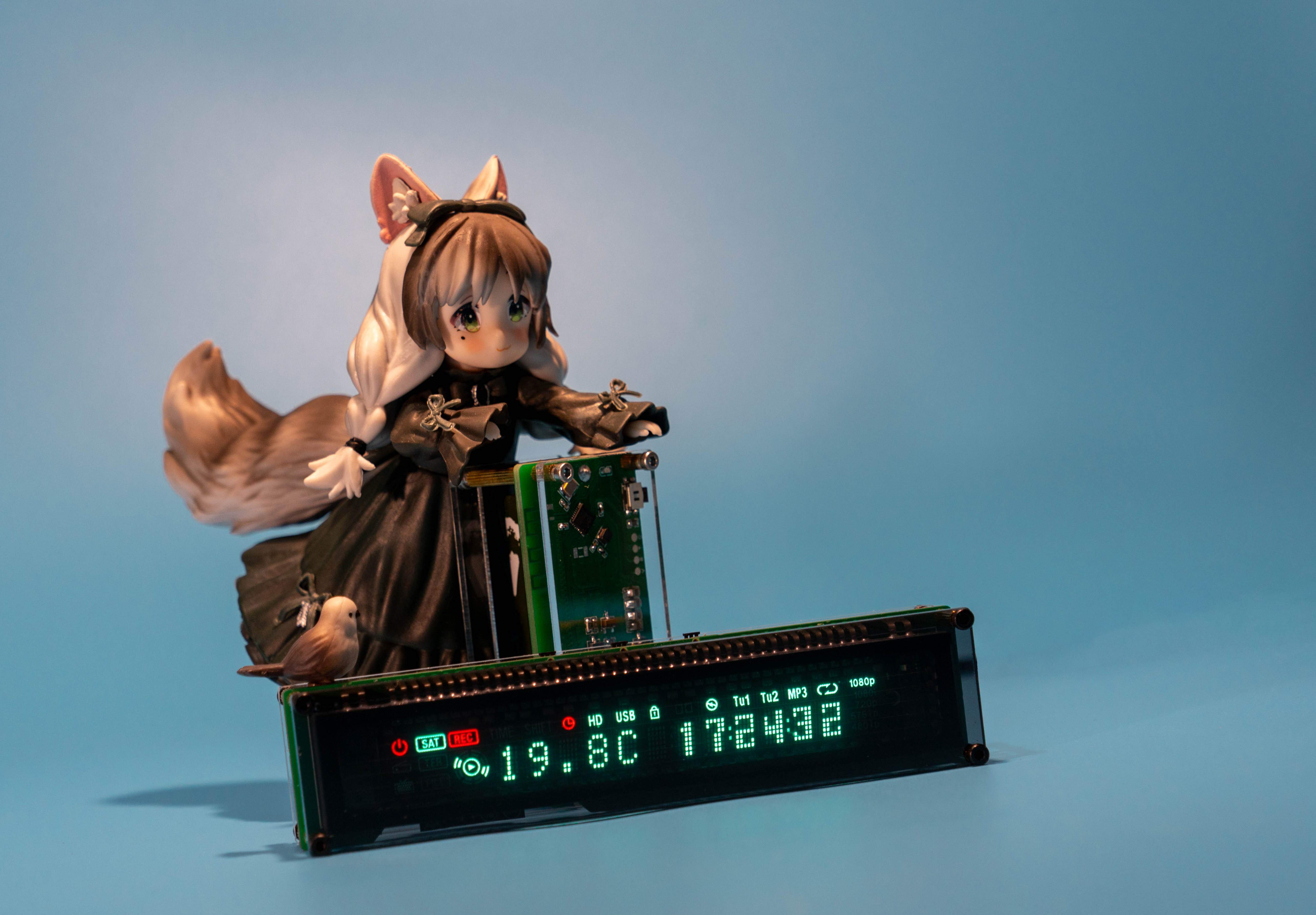
Physical Display


Design Considerations
1.Check whether there is a short circuit in the welding before inserting it into the computer to download the program.
2.After soldering other components, solder the VFD screen. Find something to pad the lower screen for soldering. Pay attention to safety when trimming the pins of the VFD screen.
3.The buzzer and three buttons cannot be washed with washing water.
4.The clock needs to be connected to wifi for 2.4G wifi, and the wifi account password is written in configuration.h.
5.If you don’t want to configure the IDF environment yourself, you can ask me to help compile a program corresponding to your own wifi account and password ( the attachment provides the firmware for wifi account “ABCB” and password “123456”, QQ group: 697752852 )
Update Record
2023-11-13: Fixed the bug that the power-on date was displayed as 1/0 and the alarm would not be triggered when the humidity exceeded 95%.
2024-09-08: Modify the low battery judgment as a percentage of battery, and modify the default wifi account password in the configuration header file.
2024-09-26: Changed the API for obtaining time, and fixed the failure to obtain time.
Demo Video
Designed by TheLight (from OSHWHub)
Design Drawing
 Empty
Empty
Comment