

 Completed
Player training robot "Day by Day" 1.0
PRO Player training robot "Day by Day" 1.0
License
:GPL 3.0
Description
0. Say nothing, the machine goes first!!!


The display video has been uploaded to Bilibili, welcome to guide:
Player Training Robot "Day by Day" 1.0 Display
All engineering information links are below the video ┗|`O′|┛~~
1. Research background:
Physical exercise can enhance physical fitness and provide a material basis for a healthy personality. The famous sports educator Mr. Ma Yuehan once said, "Sports are the best tool for cultivating a healthy personality." Many people choose to play ball during physical exercise.
Sports are used as a carrier to enhance physical fitness, so reasonable training is particularly important for a novice who has just started playing ball sports. Traditional manual training has high requirements for the coach's level and generally has high costs.
Various reasons make some ball sports enthusiasts hesitate.
Therefore, it is particularly important to develop a high-performance player training robot system to act as an "auxiliary coach" to train players!!! So there is the following player training robot "Day by Day".
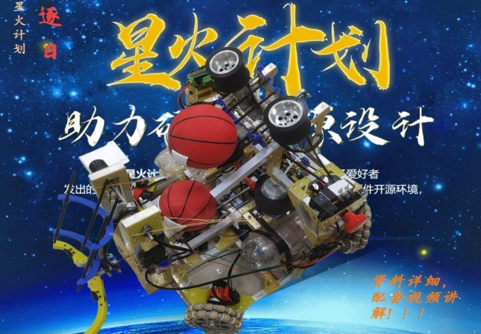
2. Machine introduction:


3. Machine structure explanation:
3.1 Moving mechanism (chassis)

1. The chassis is a relatively simple planar mechanism built of aluminum tubes. From the explosion view, it can be seen that the main components are four sets of M3508 brushless motors, C620 motor governors, aviation engines omnidirectional wheels and a positioning system module.
2. The yellow connecting piece is processed by the engraving machine epoxy plate.
3.2 Lower launch mechanism

1. Aluminum tube frame;
2. The friction wheel drive motor is M3508, which is driven by the undecelerated high-speed end;
3. The push ball cylinder is selected from the CDJ2KB series non-spinning cylinder, and one can achieve the desired function;
3.3 Upper launch mechanism

1. Aluminum tube frame;
The friction wheel drive motor is MN5212, and the motor driver uses the open-source odrive.
3. The push ball cylinder is selected from the CDJ2KB series non-spinning cylinder, and one can achieve the desired function;
3.4 Ball-taking mechanism

1. Aluminum tube frame;
2. The actuator of the ball-catching mechanism is a finger cylinder;
3. The flipped driving motor is M3508.
4. Explanation of the main mechanism control principle of the machine:
4.1 Moving mechanism (chassis) ---- omnidirectional wheel chassis **********************************************************************************************************************************
The omnidirectional wheel chassis can achieve omnidirectional movement , as shown in the figure.

Is this what is called omnidirectional movement ?
Do not!

Achieving the above movement is the specialty of omnidirectional wheels, so how to achieve it?
The following will explain in detail the control of the omnidirectional wheel chassis, GO!


At this point, we have completed all the derivations.
If you persist until here, congratulations, you are not far from success!!!


OK, after verifying and improving the chassis control algorithm through the above simulation software, the debugging of the physical object can be started.
The embedded software development platforms used in the development of this machine are Keil uVision5 and STM32CubeMX.
The code is accompanied by comments, corresponding to the code of the simulation software CoppeliaSim, which should be easy to understand and not explained too much.


Here, the control algorithm of the omnidirectional wheel chassis has been explained! If you have any questions, please leave a message.
I believe that by referring to the above tutorial, everyone can have their own true omnidirectional mobile chassis .
4.2 Launching mechanism ---- friction wheel launch


The trajectory of the friction wheel is difficult to achieve very stability, which means it will be misaimed when aiming and launching. What factors will affect the launch of the projectile?
3. Stability influencing factors: friction wheel material, friction emission structure form, size and spacing, friction wheel motor, friction wheel electric adjustment (electronic governor).
Friction wheel material
1. Silicone friction wheel:
Early friction wheels were made of silicone, but when the friction wheel was running at high speed, the part in contact with the projectile was prone to expansion due to centrifugal force and friction. If steel wire was not used for circumferential reinforcement, after long-term friction, the silicone wheel would easily fall off under the action of tangential force.
2. Polyurethane friction wheel:
How to solve the problem of friction wheel falling off? In the manufacturing industry, there is an important process called rubber roller process. It uses metal and other materials as the core and covers the outside with a rubber roller-like object (donut is a kind of roller-like object). It can well combine rubber and metal together to avoid falling off.

The material of the outer rubber coating is polyurethane, which is polymerized from polyester (or polyether) and diisocyanate lipid compounds. It has the advantages of wear resistance, tear resistance, and aging resistance, and is very suitable as a friction wheel for competitions.
Friction emission structure form
Change the friction emission structure form???
Yes, in order to obtain reliable friction acceleration effect, friction emission has evolved many new structures from the initial double friction wheel.

-----------------------------------------------------------------------------------------------------------------------------

-----------------------------------------------------------------------------------------------------------------------------

Dimensions and spacing
If the size of the friction wheel is too large and the spacing is too small, the first shot will be subjected to a great squeezing force to achieve a high firing rate, but at the same time, the reaction force on the friction wheel will also reduce its own speed, resulting in a significant reduction in the firing rate of the .
This problem is very obvious when we need to shoot at a very high frequency, and it is also one of the important reasons for the instability of the friction wheel trajectory.
Friction wheel motor
The greater the torque and moment of inertia of the motor driving the friction wheel, the smoother the rotation and the more stable the trajectory. However, the weight of the motor with greater force will also increase. If the weight of the launching mechanism is too large, it is difficult to control it to aim quickly.
Friction wheel electric adjustment (electronic governor)
We can detect the rotational speed of the friction wheel in real time through the encoder and feedback , and finally control the rotational speed by electric adjustment, so as to realize the detection and control of the rotational speed of the friction wheel.
Some ESC internal algorithms are better and can effectively control the motor speed without feedback.
You can use the open source odrive driver solution:

4.3 Launch mechanism 2nd generation
In order to obtain reliable friction acceleration effect, friction emission has evolved from the initial double friction wheel to many new structures
Double friction wheel structure:

--------------------------------------------------------------------------------------------------------------------------------------------------------------------------------------------------------------------------

----------------------------------------------------------------------------------------------------------------------------------------------------------------------------------------------

-----------------------------------------------------------------------------------------------------------------------------------------------------------------------------------------------

"Day by day" launch mechanism (2nd generation) was born!!!

**********************************************************************************************************************************************************************************************

**********************************************************************************************************************************************************************************************

**********************************************************************************************************************************************************************************************

**********************************************************************************************************************************************************************************************

**********************************************************************************************************************************************************************************************

Designed by 破晓修行monarch (from OSHWHub)
Link:https://oshwhub.com/eda_zbyucrfj/qiu-yun-xun-lian-ji-qi-ren-1.0
Design Drawing
 Empty
Empty
Comment